I2C Protocol
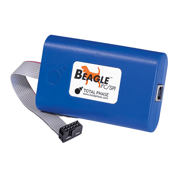
I2C is a two-wire, open-drain serial bus for short links between chips on the same board: one clock line (SCL), one data line (SDA), 7-bit addresses and speeds from 100 kbit/s to 3.4 Mbit/s. To see what is on the wire, use a protocol analyser such as the Beagle I2C/SPI, which monitors I2C to 4 MHz without driving the bus, or a logic analyser with an I2C decoder. To act as the controller or a target from a PC, use a host adapter such as the Aardvark.
How the I2C Bus Is Wired
Every device on the bus connects to the same two lines. In Standard-mode, Fast-mode and Fast-mode Plus, no device drives a line high: each one can only pull it low, and a pull-up resistor (Rp) on each line returns it high when nobody is pulling. This open-drain arrangement is what lets several devices share a wire without contention, and it is also why the pull-up value and the total bus capacitance decide how fast the bus can run.
The controller (called the master in older documents) generates the clock and starts every transfer. Targets (formerly slaves) answer when they see their own address. A bus can have more than one controller; if two start at once, arbitration on SDA decides which one carries on, and the other backs off without corrupting the message.
How an I2C Transfer Works
- START: the controller pulls SDA low while SCL is high. Every target starts listening.
- Address and direction: seven address bits, most significant bit first, then one R/W bit: 0 to write, 1 to read.
- Acknowledge: on the ninth clock the addressed target pulls SDA low (ACK). If SDA stays high (NACK), no target acknowledged the address.
- Data: eight bits per byte, each followed by an ACK or NACK from whichever side is receiving.
- STOP or repeated START: SDA rises while SCL is high to release the bus. A repeated START instead lets the controller change direction, for example write a register number and then read it back, without letting another controller take the bus.
A target that needs more time can hold SCL low after a byte. This is clock stretching, and the controller must wait until SCL is released before it continues.
Speed Modes
| Mode | Maximum Bit Rate | Direction | Bus Capacitance Limit |
|---|---|---|---|
| Standard-mode (Sm) | 100 kbit/s | Bidirectional | 400 pF |
| Fast-mode (Fm) | 400 kbit/s | Bidirectional | 400 pF |
| Fast-mode Plus (Fm+) | 1 Mbit/s | Bidirectional | 550 pF |
| High-speed mode (Hs) | 3.4 Mbit/s | Bidirectional | 100 pF at 3.4 Mbit/s, 400 pF at 1.7 Mbit/s |
| Ultra Fast-mode (UFm) | 5 Mbit/s | Controller to target only, push-pull, no acknowledge | Not specified in the same way |
From NXP UM10204, the I2C-bus specification and user manual.
Choosing the Pull-Up Resistors
The resistor has a minimum and a maximum. Too small, and a device cannot pull the line below its low threshold: Rp(min) = (VDD − VOL(max)) / IOL. Too large, and the line rises too slowly through the bus capacitance: Rp(max) = tr / (0.8473 × Cb), where tr is the maximum rise time for the mode (1000 ns in Standard-mode, 300 ns in Fast-mode, 120 ns in Fast-mode Plus). Fit one resistor per line for the whole bus, not one per device, and remember that many breakout boards carry their own pull-ups, which then appear in parallel.
Where I2C Is Used
- Sensors: temperature, humidity, pressure, accelerometers and gyroscopes, ambient light.
- Configuration memory: 24-series serial EEPROMs, and the SPD EEPROM on memory modules.
- Power management: PMICs, voltage regulators and battery fuel gauges, often through SMBus and PMBus, which are built on I2C.
- Displays and video: the DDC channel on HDMI, DVI, DisplayPort adapters and VGA carries the monitor's EDID over I2C, and many small OLED and LCD panels take commands over I2C.
- Clocks, I/O and control: real-time clocks, GPIO expanders, touch controllers, audio codec control ports and camera sensor control interfaces.
Common I2C Faults and How to Find Them
| Symptom | Likely Cause | What to Check |
|---|---|---|
| Every transfer is NACKed | Wrong address, often a 7-bit address given in 8-bit form (0xA0 instead of 0x50), or the target is unpowered or held in reset | Decode the address byte with an analyser and compare it with the datasheet |
| SDA stuck low | A target was interrupted mid-byte, for example by a controller reset, and is still waiting for clocks | Send nine clock pulses on SCL; if SDA stays low, reset or power-cycle the target (the bus clear procedure in UM10204) |
| Works at 100 kHz, fails at 400 kHz | Rise time too slow: pull-ups too weak for the bus capacitance | Measure the rising edge on an oscilloscope; reduce Rp within the Rp(min) limit, or shorten the bus |
| Intermittent corrupt bytes | A target stretches the clock and the controller does not support it, or noise on long wiring | Look for SCL held low after the ACK in a capture; check the controller's clock-stretching support |
| Two devices answer at once | Address conflict between two parts of the same type | Change the address-select pins, or split the bus with an I2C multiplexer |
| Nothing works with a 1.8 V target | Logic levels do not match the tool or the other devices | Use a level shifter, or a tool with an adjustable I/O voltage |
Tools for Analysing and Decoding I2C
Choose by what you need to do. Watch tools listen to an existing bus and record every transaction with timestamps, without changing what is on the wire. Drive tools take the place of the controller or a target, so you can talk to a device before the firmware exists, or script production tests.
Protocol Analysers
Built for one job: capture I2C traffic, decode it to addresses, reads, writes, ACK and NACK, and show it as a transaction list you can search and filter.
| Product | Role | I2C Capability | Price ex VAT |
|---|---|---|---|
| Total Phase Beagle I2C/SPI (TP320121) | Watch | Non-intrusive monitor of I2C to 4 MHz, with SPI and MDIO on the same unit | £400 |
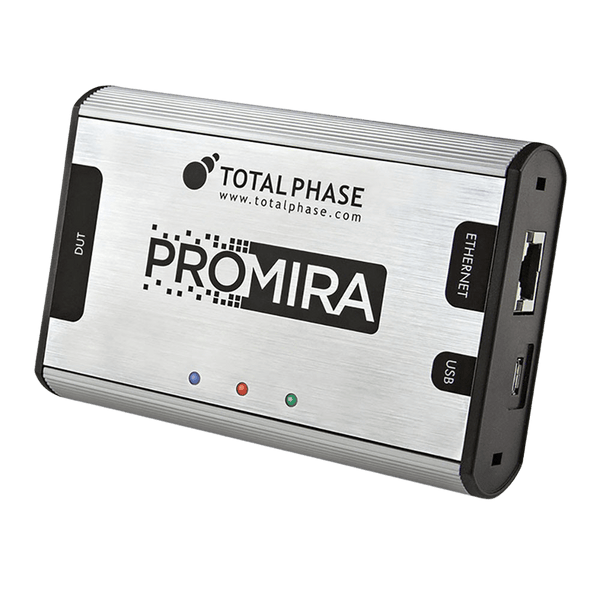
| Total Phase Promira with the I2C Analysis application (TP601110) | Watch | Monitors I2C to 5 MHz; add I2C Active applications to drive the bus from the same unit | £1,040 plus £120 |
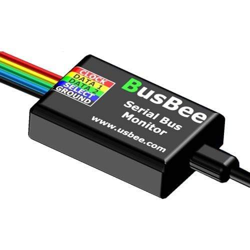
| CWAV BUSBee | Watch | Serial bus analyser that lists I2C among its supported buses | £170.24 |
Logic Analysers With I2C Decoding
The better choice when I2C is one of several signals you need to see together, for example an interrupt line, a chip select or a GPIO toggled by firmware alongside the bus.
| Product | Role | I2C Capability | Price ex VAT |
|---|---|---|---|
| Saleae Logic 8 | Watch | 8 channels, digital and analogue; I2C decoder in the Logic 2 software | £405 |
| Saleae Logic Pro 8 | Watch | 8 channels at higher sample rates; same I2C decoder | £830 |
| Saleae Logic Pro 16 | Watch | 16 channels; same I2C decoder | £1,245 |
| Acute TravelBus TB3016 Series | Watch | Bus analyser with I2C trigger and decode, I2C to 400 kHz | From £183.96 |
| ZeroPlus LAP-C Pro Series | Watch | Logic analyser with I2C protocol analysis | From £925 |
| Micsig TO Series tablet oscilloscope | Watch | Oscilloscope with I2C decoding as standard, so you see edge quality and decoded bytes together | From £520 |
Host Adapters
| Product | Role | I2C Capability | Price ex VAT |
|---|---|---|---|
| Total Phase Aardvark (TP240141) | Drive | I2C controller or target to 800 kHz from a PC, with switchable 2.2 kΩ pull-ups; also SPI | £335 |
| Promira with I2C Active Level 1 (TP600110) | Drive | I2C controller and target to 1 MHz | £120 plus the Promira |
| Promira with I2C Active Level 2 (TP600210) | Drive | I2C controller and target to 3.4 MHz | £650 plus the Promira |
Connecting to the Bus
- TP240212 10-Pin Split Cable (£50): splits the Total Phase 10-pin connector into individual labelled leads, so you can reach SDA, SCL and ground test points on boards without the 10-pin header.
- TP240610 Level Shifter Board (£175): for 1.2 V to 3.3 V targets with the 3.3 V Aardvark and Beagle.
- DDC breakout cables for monitoring EDID traffic: DVI (£100) and VGA (£100).
- TP240310 I2C/SPI Activity Board (£80): a known-good I2C and SPI target for learning a tool or proving a test set-up.
Browse every tool in our protocol decoders, logic analysers and host adapters collections. Not sure which fits your bus speed and voltage? Send us the target device and bus rate and we will recommend one.
Frequently Asked Questions
What Is the Difference Between I2C and SMBus?
SMBus uses the same two-wire bus but adds rules I2C does not have: a clock timeout so a stuck device cannot hold the bus forever, a minimum clock rate, fixed logic thresholds and optional packet error checking. Most devices interoperate at 100 kHz, but check the timeout and voltage thresholds before mixing them.
How Many Devices Can I Connect to One I2C Bus?
Two limits apply: the address space (7-bit addressing leaves 112 usable addresses after the reserved ones) and the bus capacitance (400 pF in Standard-mode and Fast-mode). In practice capacitance and duplicate addresses run out first; an I2C multiplexer solves both; a bus buffer solves capacitance only.
Why Does My Datasheet Give an 8-Bit Address?
Some datasheets quote the address byte with the R/W bit included, so a 7-bit address of 0x50 appears as 0xA0 for a write and 0xA1 for a read. Analysers and most software libraries expect the 7-bit form.
Do I Need a Protocol Analyser or Will a Logic Analyser Do?
A logic analyser with an I2C decoder is enough to see addresses, data and ACKs alongside other signals. A dedicated protocol analyser such as the Beagle I2C/SPI records long sessions as a searchable transaction list with precise timestamps, which is faster when you are hunting one bad transfer among thousands.
What Pull-Up Resistor Value Should I Use?
There is no single value. Work out the minimum from the supply voltage and the sink current of the weakest device, and the maximum from the rise time allowed for your speed mode and the measured bus capacitance. Values between 1 kΩ and 10 kΩ are typical; faster modes and longer buses need the lower end.
Where to Start with I2C
More Protocols
By John Legg CEng, Director, Debug Store. Updated 3 November 2026.
