
Tag-Connect, LLC
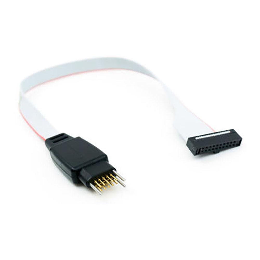
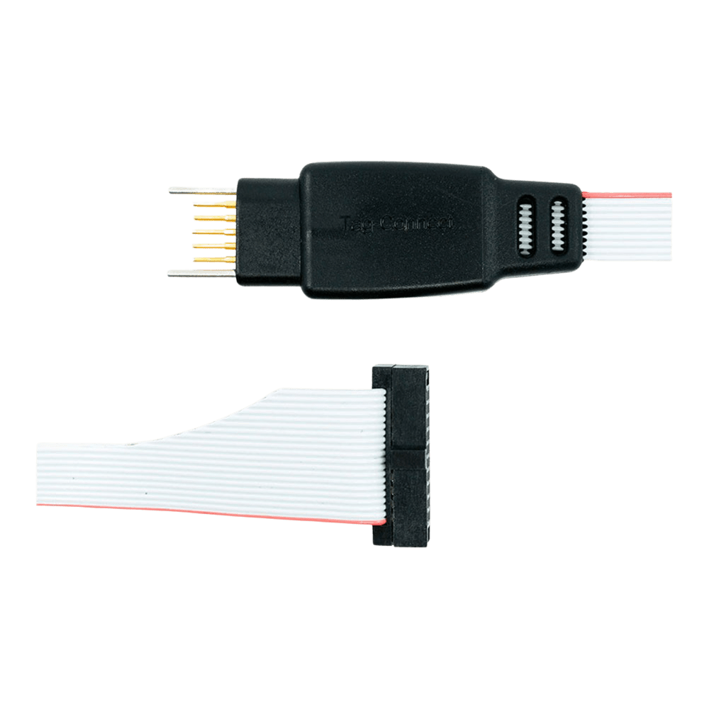
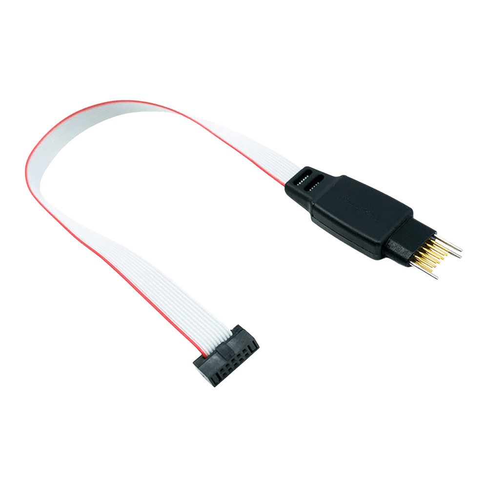
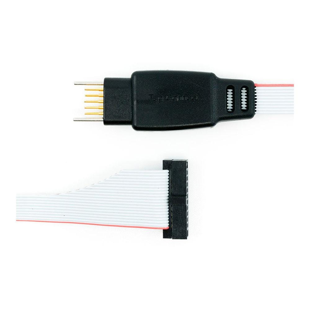
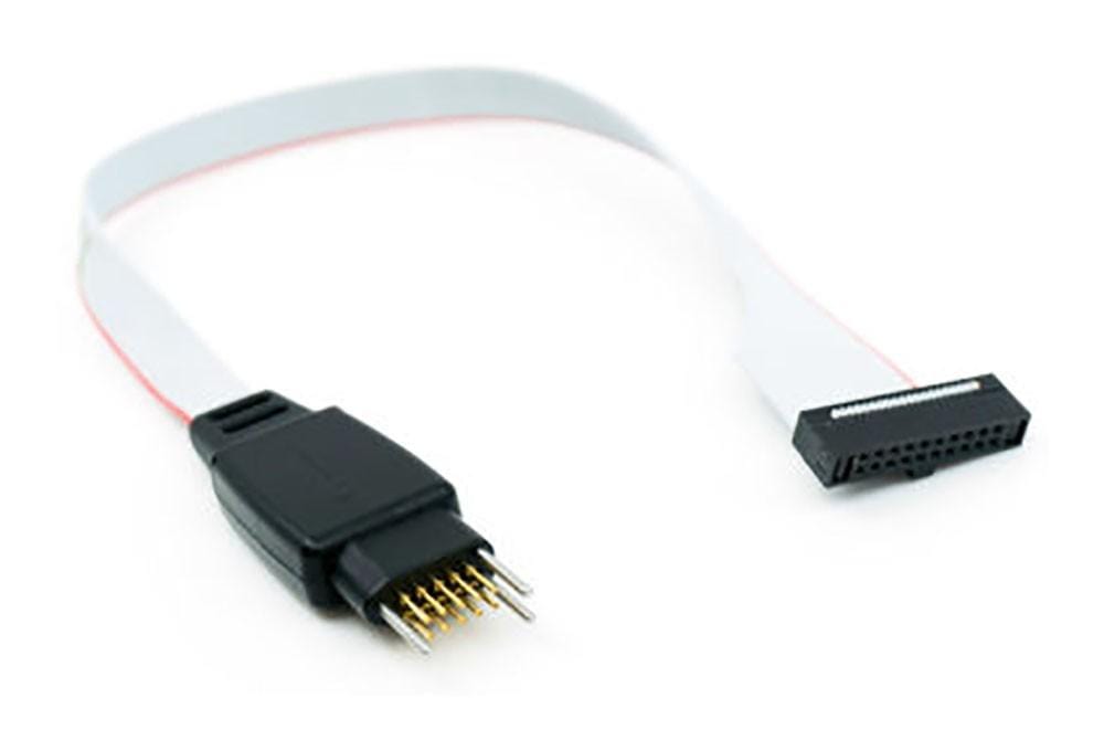
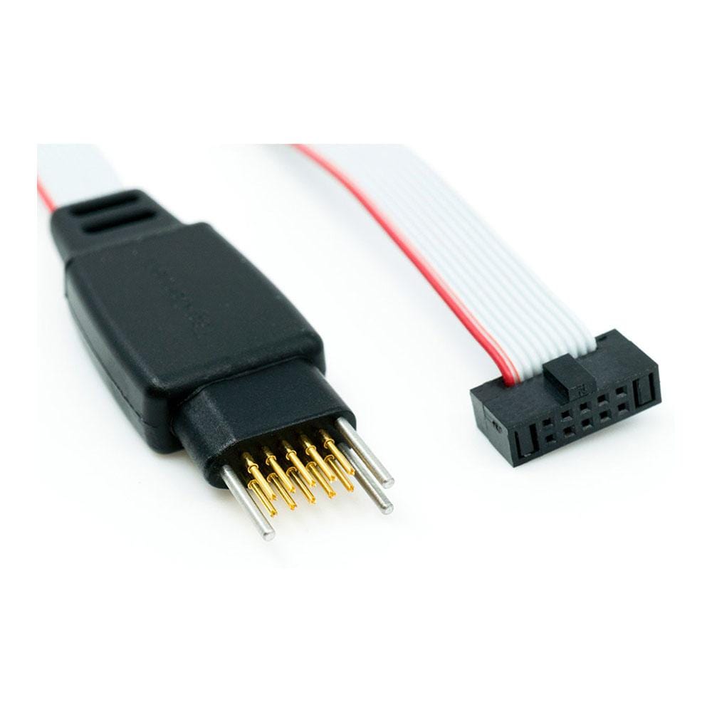
Tag-Connect TC2050-IDC-NL-050-ALL-20 10-Pin No Legs Cable for 20-Pin 0.05 in Cortex Debug
Tag-Connect TC2050-IDC-NL-050-ALL-20 10-Pin No Legs Cable for 20-Pin 0.05 in Cortex Debug
SKU: TC2050-IDC-NL-050-ALL-20
£68.00 exc VAT
Four legs clip into latch holes on the board, so the cable stays in place hands-free. Best for development and debugging.
Fits a smaller footprint (about 0.03 sq in) with no leg latch holes. For production programming, and for debugging when held in place with a TC2050-CLIP or in a fixture.
Suggested Add-Ons
Optional. Tick any you need. One of each is added to your cart with this item, whatever the quantity.
Check and Add to Cart
Confirm the price and stock for your selection, set the quantity, then press Add to Cart.
Payment methods
Couldn't load pickup availability
Key Features
Overview
The Tag-Connect TC2050-IDC-050-ALL-20 links a probe with the 20-pin 0.05 in Cortex Debug + ETM header to ten pads on your PCB. Pins 1 to 10 are wired 1-to-1, so SWD and JTAG reach the target; pins 11 to 20 (parallel trace, extra grounds and, on some probes, target power) are not connected.
Choose the head in the options above.
The Legged version clips into the footprint and stays in place without a fixture. The No Legs version needs about 0.03 sq in and is held by hand, with a TC2050-CLIP or in a fixture. For a 10-pin 0.05 in probe use the TC2050-IDC-050-ALL.
Downloads
Ten Pads on Your PCB to a 20-Pin 0.05 in Cortex Debug Probe
The Tag-Connect TC2050-IDC-050-ALL-20 connects a debugger with the 20-pin 0.05 in (1.27 mm) Cortex Debug + ETM header, the Samtec FTSH-110 style micro-header, to a 10-pad TC2050 footprint on your PCB, with no connector fitted to the board. Pins 1 to 10 are wired 1-to-1 to the ten pads, so SWD and JTAG reach the target. Pins 11 to 20, which on the 20-pin header carry the trace clock and data, extra grounds and, on some probes, a target power feed, are not connected.
Options
| Option | Choice | Detail |
|---|---|---|
| Head | Legged | Four legs latch into holes in the PCB, so the cable holds itself in place |
| Head | No Legs | No leg holes; footprint about 0.03 sq in; hold by hand, with a TC2050-CLIP or in a fixture |
TC2050-IDC-050-ALL-20 Pinout
TC2050 pad n goes to connector pin n for pins 1 to 10. Signals follow the Arm Cortex Debug connector:
| Pad and Pin | Signal | Pad and Pin | Signal |
|---|---|---|---|
| 1 | VTref | 2 | SWDIO / TMS |
| 3 | GND | 4 | SWCLK / TCK |
| 5 | GND | 6 | SWO / TDO |
| 7 | Key (no signal) | 8 | TDI |
| 9 | GNDDetect | 10 | nRESET |
Connector pins 11 to 20 are not connected, so parallel trace (TRACECLK and TRACEDATA) is not available through this cable, and a probe that feeds target power on pins 11 and 13 cannot power the target through it. SWO on pin 6 is connected.
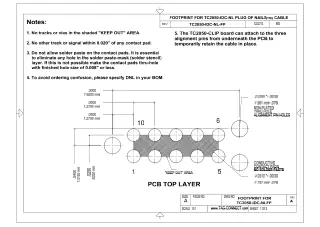
On the footprint the pads are numbered 1 to 5 along one row and 6 to 10 back along the other, so pad 10 sits opposite pad 1. They are not arranged odd and even like the header: follow the footprint drawing.
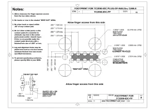
PCB footprint: ten contact pads at 0.05 in pitch and three alignment holes; the Legged footprint adds four leg latch holes. Keep solder paste off the contact pads. The footprint drawings are in the TC2050-IDC (Legged) and TC2050-IDC-NL (No Legs) datasheets under Downloads. See also our Tag-Connect cable guide.
Spring-Pin Contacts
Tag-Connect quotes over 100,000 operations for the TC2050 spring pins. The 0.05 in connector uses fine-pitch ribbon with thin conductors, which Tag-Connect says can break over time with repeated flexing, so avoid sharp bends and repeated flexing at the connector.
Who It's For
Engineers who program or debug Arm Cortex boards over SWD or JTAG from a probe with the 20-pin 0.05 in Cortex Debug + ETM header, and want no debug header on the PCB.
| Device Family | Debugger or Programmer | Connection |
|---|---|---|
| Arm Cortex-M devices, SWD or JTAG | Keil ULINKpro | Direct, on the 20-pin 0.05 in Cortex Debug + ETM header inside the probe (remove the cover) |
| Arm Cortex devices, SWD or JTAG | IAR I-jet | Direct, on the I-jet's MIPI-20 (20-pin 0.05 in) connector; parallel trace is not carried |
The Keil ULINK2 and ULINKplus have the 10-pin 0.05 in Cortex Debug connector: use the TC2050-IDC-050-ALL instead.
Limitations
Not the right cable when you need parallel trace: only pins 1 to 10 are connected. Not for a debugger with only the 20-pin 0.1 in Arm JTAG header (use the TC2050-IDC with the TC2050-ARM2010 adapter), or for a Microchip Atmel-ICE (use the TC2050-IDC-050-ALL with the Ribbon option set to LEMTA, which has the ribbon connector fitted reversed).
Compare the Versions
| Part Number | Head | Footprint | Best For |
|---|---|---|---|
| TC2050-IDC-050-ALL-20 | Legged | Ten pads, three alignment holes and four leg latch holes | Development and debugging: clips in and stays connected hands-free |
| TC2050-IDC-NL-050-ALL-20 | No Legs | Ten pads and three alignment holes, about 0.03 sq in | Production programming, or debugging with a TC2050-CLIP; smallest footprint |
Both versions use the same ten-pad contact pattern and the same wiring; only the head differs.
Which cable fits your debugger? See our Tag-Connect cable guide.
| Ordering information | |
|---|---|
| Part number (SKU) | TC2050-IDC-NL-050-ALL-20 |
| Manufacturer | Tag-Connect, LLC |
| EAN | 5055383665488 |
| Warranty | 6 months |
| Shipping weight | 0.1 kg |
- 1 ×Tag-Connect TC2050-IDC-050-ALL-20 cable, Legged or No Legs as selected
Cable only. No debugger, adapter, retaining clip or fixture is included. On the No Legs version, the TC2050-CLIP retaining clip and the TC2050-MOUNT fixture are offered as add-ons.
Questions and Answers
-
How Do I Create the PCB Footprint for This Cable?
Download the TC2050-IDC (Legged) or TC2050-IDC-NL (No Legs) datasheet for exact pad dimensions, hole sizes and spacing. Both are under Downloads on this page.
-
Is This Cable Suitable for Production Programming?
Yes. Tag-Connect recommends the No Legs version (TC2050-IDC-NL-050-ALL-20) for production, where short connection times matter, and the Legged version for development. Tag-Connect rates the TC2050 spring pins for over 100,000 operations, and notes that the fine 0.05 in ribbon can break with repeated flexing.
-
Can I Use This with 3.3 V Target Systems?
Yes. The cable is passive, so it works at any target voltage your debugger supports. Pin 1 carries the target voltage reference to the debugger; it is not a power supply.
-
What Signals Are Available on the TC2050 Footprint?
Pins 1 to 10 of the 20-pin connector pass straight through to the ten pads: VTref (1), SWDIO/TMS (2), GND (3 and 5), SWCLK/TCK (4), SWO/TDO (6), key (7, no signal), TDI (8), GNDDetect (9) and nRESET (10). Pins 11 to 20 are not connected.
-
How Does This Compare to Traditional 20-pin JTAG Headers?
It removes the connector cost of a traditional 20-pin JTAG header, carrying the JTAG/SWD signals on pins 1-10 of the header (pins 11-20 are not connected).
Traditional 20-pin header This cable and footprint Connector on the board Fitted on every board None; per-board cost of the footprint is zero Board space Depends on the header About 0.03 sq in for the No Legs footprint Signals carried Pins 1-20 Pins 1-10 (pins 11-20, including parallel trace, not connected) -
What Debuggers Are Compatible with the TC2050-IDC-050-ALL-20 Cable?
Tag-Connect recommends it for the IAR I-jet and the Keil ULINKpro (on the ULINKpro's internal 20-pin header, under the cover), and for other debuggers with the 20-pin 0.05 in Cortex Debug + ETM (MIPI-20) connector, the Samtec FTSH-110-01 style micro-header. The Keil ULINK2 has the 10-pin 0.05 in Cortex Debug connector, so use the TC2050-IDC-050-ALL with it.
-
How Does This Differ From the Standard TC2050-IDC-050 Cable?
This cable connects all 10 TC2050 pins one-to-one, whereas the standard TC2050-IDC-050 leaves two pins open.
Cable TC2050 pins 5 and 9 Other pins TC2050-IDC-050-ALL-20 (this cable) Connected All 10 connected 1-1; pins 11-20 of the 20-pin connector not connected TC2050-IDC-050 Not connected Pins 1-4, 6-8 and 10 connected -
What PCB Thickness Range Is Supported?
Tag-Connect does not publish a thickness range for the standard legs. Its LONGLEGS version is recommended for boards over 1.6 mm (0.063 in) thick and works up to 3.2 mm (0.126 in), so treat about 1.6 mm as the practical limit for the standard legs.
Legs PCB thickness Standard legs (Legged version) Up to about 1.6 mm (0.063 in); no range published TC2050-IDC-LONGLEGS Over 1.6 mm, up to 3.2 mm (0.126 in) Tag-Connect lists no LONGLEGS version of this 20-pin cable; its long-leg TC2050 cable is the TC2050-IDC-LONGLEGS.
-
Can I Use This Cable with STM32 Microcontrollers?
Yes, provided your debugger has a Cortex-20 header with 0.05 in pitch. The cable carries the Cortex debug signals on pins 1-10, so check that your debugger uses that connector. Tag-Connect's STM32 and ST-LINK solutions use other cables (STDC14 or ARM20).
-
What's the Difference Between the Legged and No Legs Versions?
The Legged version has four plastic legs that latch into the PCB for a secure hands-free connection. The No Legs version must be held by hand or used with the TC2050-CLIP.
Legged No Legs Hold on the PCB Secures itself with plastic legs Held by hand, or with a TC2050-CLIP Footprint Adds four leg holes Pads and alignment holes only, about 0.03 sq in Tag-Connect suggests it for Development needing a secure connection over time Production programming, especially short one-off operations


No questions match your search.