
Acute Technology, Inc
Acute Technology LA4000 Plus Serie 68/136-Kanal-Logikanalysator
Acute Technology LA4000 Plus Serie 68/136-Kanal-Logikanalysator
SKU: LA4068E
From £7,100.00 exc VAT
Check and Add to Cart
Confirm the price and stock for your selection, set the quantity, then press Add to Cart.
Zahlungsmethoden
- Banküberweisung
Verfügbarkeit für Abholungen konnte nicht geladen werden
Key Features
Overview
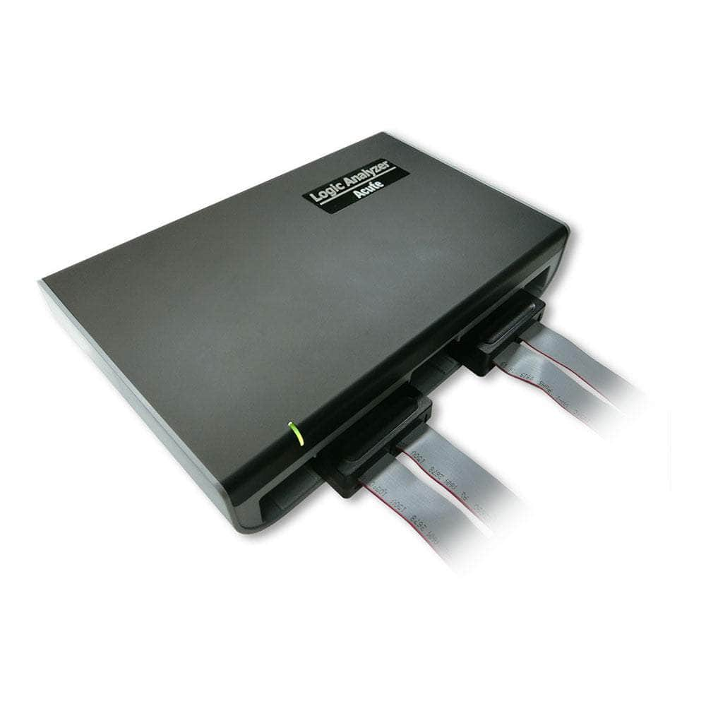
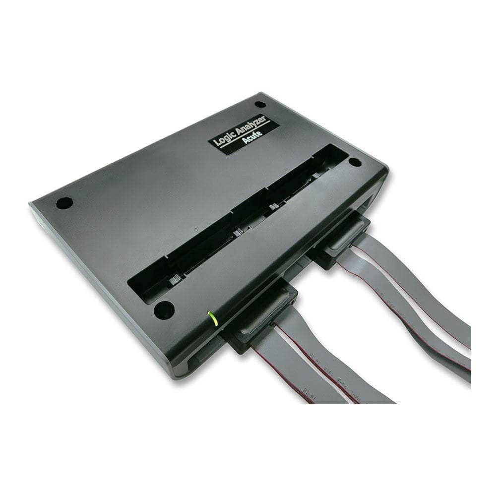
Acute Technology LA4000 Series Logic Analyzer
The Acute Technology LA4000 Series is a PC-based logic analyzer designed for demanding signal analysis and protocol debugging applications. With up to 136 channels and sample rates reaching 4 GHz timing and 400 MHz state analysis, it meets the requirements of complex digital designs, including FPGAs, ADCs, and advanced communication interfaces. The series offers models such as LA4068B/E and LA4136B/E, providing both 68 and 136 channel options tailored to your application's needs. A 32 GB memory depth supports extensive data capture for long or critical events, and the device connects via USB 3.0 for reliable, high-speed data transfers.
Engineers benefit from wide protocol support, enabling analysis and decoding of over 100 protocols like I²C, SPI, CAN, UART, and newer standards including eSPI and MIPI I3C. Unique trigger and storage options, such as parallel clause triggers and real-time protocol monitoring, facilitate fast troubleshooting and deep debug insight. The LA4000 can stack with oscilloscopes from leading brands, expanding it into a powerful mixed-signal verification tool.
For those looking for performance above rivals like Saleae, Tektronix, and Agilent/Keysight, the LA4000 stands out with higher channel count, broader memory and robust voltage range—making it ideal for capturing rare, high-speed faults across large embedded systems. Compatible with LA3000+ probes, it eases upgrades and preserves your hardware investment.
Downloads
Datasheets
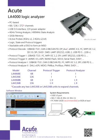
User Manuals
- Details
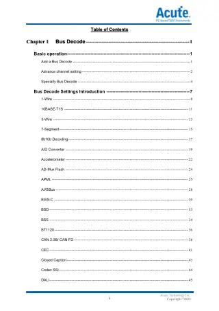 Acute Bus/Trigger Decoder ManualAcute DeTrig Series Bus/Trigger Decoder User Manual, Version 2018. Comprehensive guide covering supported bus types and trigger functions.
Die LA4000-Serie zeichnet sich im Vergleich zum LA3000+ sowohl bei der Timing-Analyse als auch bei der Zustandsanalyse aus. Das Modell LA4000 erreicht eine Frequenz von 4 GHz bei der Timing-Analyse und beeindruckende 400 MHz bei der Zustandsanalyse und ist damit die ideale Wahl für die Logikanalyse bei Hochgeschwindigkeitsdatenübertragung, Kommunikationsprotokollanalyse und die Handhabung komplexer Signalstrukturen.
Der Logikanalysator LA4128B ist ein vielseitiges Werkzeug, das mit seinen 136 Kanälen umfassende Unterstützung bietet. Er deckt verschiedene Anwendungsszenarien ab, von der Analyse von Signalstrukturen bis hin zur Dekodierung und Fehlerbehebung von Kommunikationsprotokollbussen. Insbesondere das Modell LA4128B zeichnet sich durch seine robuste Leistung aus und ist daher die ideale Wahl für Aufgaben im Zusammenhang mit der Entwicklung und Fehlerbehebung von ADC- und FPGA-Chips.
Each protocol links to our guide where one exists. The Decoding Levels tab explains each type of support. Key:
- D Software protocol decode
- T Hardware protocol trigger
- A Protocol analyser mode (hardware decode and record, no waveform)
| Protocol | LA4068E | LA4136E | LA4068B | LA4136B |
|---|---|---|---|---|
| Embedded Serial Buses | ||||
| 1-WireSingle-wire bus with data and ground only, used for ID chips, EEPROMs and sensors. | D | D | D | D |
| 3-WireSerial link with chip select, read/write strobes and one data line, used by LED, LCD and EEPROM chips. | D | D | D | D |
| HDQTI single-wire interface used by battery fuel gauges. | D | D | D | D |
| HID over I2CHID reports from keyboards, touch panels and other input devices carried over I2C.Trigger on: address, R/W, ACK and data, or a HID descriptor read. | DTA | DTA | DTA | DTA |
| HID over SPIHID reports from keyboards, touch panels and other input devices carried over SPI. | D | D | D | D |
| I2CTwo-wire bus (SCL, SDA) for sensors, EEPROMs and power chips.Trigger on: address, R/W, ACK and up to 4 data bytes (equal or not equal, at any or a fixed offset); timing violations, clock stretching and timeouts. | DTA | DTA | DTA | DTA |
| I2C (EEPROM)Decodes reads and writes to 24-series I2C EEPROMs as memory addresses and data. | D | D | D | D |
| LPTPC parallel printer port. | D | D | D | D |
| Microchip SWISingle-wire interface of Microchip (Atmel) CryptoAuthentication devices. | D | D | D | D |
| MICROWIREFour-wire synchronous serial interface used mainly by 93-series EEPROMs. | D | D | D | D |
| MIPI I3C 1.2MIPI successor to I2C: two-wire, push-pull data at about 12.5 MHz, with in-band interrupts.Trigger on: START, repeated START or STOP; address, common command code (CCC) and data at any or a fixed offset. | DTA | DTA | DTA | DTA |
| MIPI RFFE 3Two-wire MIPI control bus for the RF front end of a mobile phone.Trigger on: command type, address and data. | D | D | DTA | DTA |
| MIPI SPMI 2Two-wire MIPI bus between a processor and the power management ICs in a mobile phone.Trigger on: command type, address and data; command frame and parity errors; bus timeout. | D | D | DTA | DTA |
| PS/2Two-wire clock and data interface for keyboards and mice. | D | D | D | D |
| QSPISPI with 1, 2, 4 or 8 data lines, used for LCD interfaces and peripherals. | D | D | D | D |
| RT_SWIRichtek single-wire interface, used by battery pack authentication ICs such as the RT9430. | D | D | D | D |
| SDQTI single-wire interface for serial EPROMs such as the bq2022, bq2024, bq2025 and bq2026. | D | D | D | D |
| Smart Card (ISO 7816)Contact smart card interface used by bank cards and SIMs. | D | D | D | D |
| SPIFour-wire, full-duplex bus for flash, ADCs, displays and other peripherals.Trigger on: up to 8 data bytes on Data In or Data Out, or on both lines treated as 2-bit dual data, at any or a fixed offset. | DTA | DTA | DTA | DTA |
| SSISynchronous serial interface with clock, frame sync and data, used by DSPs. | D | D | D | D |
| SWPSingle Wire Protocol linking a SIM card to an NFC controller. | D | D | D | D |
| UART (RS232)Asynchronous serial frames for consoles and modules, also carried over RS-232, RS-422 and RS-485.Trigger on: up to 16 data bytes, anywhere in the stream or at a set position. | DTA | DTA | DTA | DTA |
| UNI/OMicrochip single-wire bus for UNI/O serial EEPROMs. | D | D | D | D |
| WiegandTwo-wire interface between card readers and controllers in access control systems. | D | D | D | D |
| Automotive and Industrial | ||||
| 10BASE-T1SIEEE 802.3cg 10 Mbit/s Ethernet over a single twisted pair, with multi-drop support, for vehicles and industry.Trigger on: destination address, source address, EtherType/length and data. | DTA | DTA | DTA | DTA |
| BiSS-COpen bidirectional serial interface for absolute position encoders and motor feedback.Trigger on: CTS, command, IDL and data fields; CRC6 or CRC4 errors. | DTA | DTA | DTA | DTA |
| BSDBit Serial Device single-wire interface used in battery management. | D | D | D | D |
| BSSBit Synchronous Single-wire interface, a link between the engine ECU and the alternator voltage regulator. | D | D | D | D |
| CANMulti-master bus for vehicles and industrial control; CAN FD adds a faster data phase and larger frames.Trigger on: 11-bit ID, 29-bit ID, data, or ID plus data. | DTA | DTA | DTA | DTA |
| DALITwo-wire lighting control bus (IEC 62386) for dimmable LED drivers and ballasts.Trigger on: frame type (IEC 62386-102 or -103), command type (short address, group, broadcast, response, special command) or a custom command. | D | D | DTA | DTA |
| DMX512RS-485 based protocol for controlling stage lighting and effects. | D | D | D | D |
| FlexRayTime-triggered vehicle network at up to 10 Mbit/s for chassis, powertrain and x-by-wire systems. | D | D | D | D |
| IO-LinkPoint-to-point link (IEC 61131-9) between a master and smart sensors or actuators. | D | D | D | D |
| ISELED Digital RGBISELED bidirectional, differential two-wire daisy-chain bus for smart RGB LEDs, mainly in vehicle interior lighting. | D | D | D | D |
| J1850SAE vehicle network between ECUs, used for OBD-II diagnostics, in PWM and VPW forms. | D | D | D | D |
| LIN 2.2Single-wire, low-speed vehicle bus for body electronics such as switches and actuators.Trigger on: ID, parity, data length and data; LIN errors. | DTA | DTA | DTA | DTA |
| M-BusMeter-Bus (EN 13757) for reading heat, water, gas and electricity meters. | D | D | D | D |
| ModbusRequest-response protocol for PLCs, drives and meters, usually over RS-485.Trigger on: start or end of frame, parity error, break or idle; frame content in ASCII or RTU mode. | D | D | DTA | DTA |
| OA3p (PMD)OPEN Alliance 3-pin interface (TX, RX, EN) between a 10BASE-T1S PHY and its PMD transceiver. | D | D | D | D |
| OATC6 over SPIOPEN Alliance TC6 framing that carries Ethernet between a host and a MAC-PHY over SPI. | D | D | D | D |
| ProfibusFieldbus for factory and process automation (PROFIBUS DP and PA).Trigger on: start delimiter (SD) frame type and its fields. | D | D | DTA | DTA |
| QEIQuadrature encoder signals (A, B and index) decoded into position and direction. | D | D | D | D |
| SENTSAE J2716 one-way link that sends sensor data to the ECU as timed nibbles.Trigger on: slow channel message ID or data, or fast channel data; SENT errors. | DT | DT | DT | DT |
| Power and System Management | ||||
| APMLAMD Advanced Platform Management Link, a two-wire interface for out-of-band processor management. | D | D | D | D |
| AVSBusAdaptive Voltage Scaling Bus, a fast three-wire (clock, MOSI, MISO) link, first defined as Part III of PMBus, through which a processor adjusts its regulator voltage. | D | D | D | D |
| HDQTI single-wire interface used by battery fuel gauges. | D | D | D | D |
| MIPI SPMI 2Two-wire MIPI bus between a processor and the power management ICs in a mobile phone.Trigger on: command type, address and data; command frame and parity errors; bus timeout. | D | D | DTA | DTA |
| PECI 3.0Intel single-wire Platform Environment Control Interface for processor temperature and management data. | D | D | D | D |
| PMBusCommand set on SMBus for configuring and monitoring power supplies and converters.Trigger on: address, command and up to 4 data bytes at any or a fixed offset; packet error check (PEC) failure. | D | D | DTA | DTA |
| SMBusI2C-based bus with timeouts and packet error checking, for batteries, sensors and EEPROMs.Trigger on: address, command (SMBus, SBS or SPD format) and up to 4 data bytes at any or a fixed offset. | D | D | DTA | DTA |
| SVI2AMD Serial VID Interface 2, through which the processor sets its voltage regulator outputs.Trigger on: SVD and SVT packet fields; SVI2 errors. | D | D | DT | DT |
| SVIDIntel Serial VID, through which the processor controls its voltage regulators. Available only under an Intel CNDA. | D | D | DTA | DTA |
| PC and Server Platform | ||||
| APMLAMD Advanced Platform Management Link, a two-wire interface for out-of-band processor management. | D | D | D | D |
| eSPIIntel Enhanced SPI link from the chipset to embedded controllers, BMCs and flash, replacing LPC.Trigger on: command and response fields, data at any or a fixed offset; eSPI errors. | D | D | DTA | DTA |
| HD AudioIntel High Definition Audio link between the PC chipset and audio codecs. | D | D | D | D |
| HID over I2CHID reports from keyboards, touch panels and other input devices carried over I2C.Trigger on: address, R/W, ACK and data, or a HID descriptor read. | DTA | DTA | DTA | DTA |
| HID over SPIHID reports from keyboards, touch panels and other input devices carried over SPI. | D | D | D | D |
| LPCLow Pin Count bus from the PC chipset to Super I/O, TPM, embedded controllers and BIOS flash.Trigger on: cycle type and its parameter fields, with a data offset setting; LPC errors. | D | D | DT | DT |
| LPTPC parallel printer port. | D | D | D | D |
| LTPILVDS Tunneling Protocol and Interface between a server host board and its secure control module (DC-SCM). | D | D | D | D |
| M-PESTIOCP single-wire sideband interface that lets a server discover attached peripherals, cables or modules before boot and tunnel their sideband signals. | D | D | D | D |
| MCTP over I2C/I3C/SMBusDMTF Management Component Transport Protocol for platform management messages over I2C, I3C or SMBus. | D | D | D | D |
| PECI 3.0Intel single-wire Platform Environment Control Interface for processor temperature and management data. | D | D | D | D |
| PS/2Two-wire clock and data interface for keyboards and mice. | D | D | D | D |
| Serialized IRQScheme that passes interrupt status over one SERIRQ line, timed by the PCI clock, between legacy ISA devices, PCI devices and the system controller. | D | D | D | D |
| SGPIOFour-wire serial GPIO bus (SFF-8485) that carries drive activity, locate and fail states from a storage controller to the backplane, and drive presence back. | D | D | D | D |
| SMBusI2C-based bus with timeouts and packet error checking, for batteries, sensors and EEPROMs.Trigger on: address, command (SMBus, SBS or SPD format) and up to 4 data bytes at any or a fixed offset. | D | D | DTA | DTA |
| SVI2AMD Serial VID Interface 2, through which the processor sets its voltage regulator outputs.Trigger on: SVD and SVT packet fields; SVI2 errors. | D | D | DT | DT |
| SVIDIntel Serial VID, through which the processor controls its voltage regulators. Available only under an Intel CNDA. | D | D | DTA | DTA |
| USB4/TBT3 SB ChannelSideband channel between USB4 or Thunderbolt 3 ports that handles link setup before the high-speed lanes start. | D | D | D | D |
| Memory and Storage | ||||
| 8b10bLine code that maps each byte to a 10-bit symbol for DC balance on high-speed serial links. | D | D | D | D |
| A/D Mux FlashParallel flash with address and data multiplexed on the same pins. | D | D | D | D |
| HyperBusEight-bit DDR interface for HyperFlash and HyperRAM memories.Trigger on: command/address bits and data. | D | D | DT | DT |
| I2C (EEPROM)Decodes reads and writes to 24-series I2C EEPROMs as memory addresses and data. | D | D | D | D |
| IDEParallel ATA (ATA-1 to ATA-7) hard disk and storage interface. | D | D | D | D |
| MICROWIREFour-wire synchronous serial interface used mainly by 93-series EEPROMs. | D | D | D | D |
| MMC/eMMCCommand, response and data lines of MMC cards and embedded eMMC storage.Trigger on: command and response fields; CRC7 or CRC16 errors; data and busy timeouts. | D | D | DT | DT |
| NAND FlashParallel NAND flash interface (ONFI or Toggle) that carries commands, addresses and data over a shared 8 or 16-bit I/O bus, using the CLE and ALE latch signals.Trigger on: command, address and data; busy time longer than a set limit. | D | D | DT | DT |
| QSPISPI with 1, 2, 4 or 8 data lines, used for LCD interfaces and peripherals. | D | D | D | D |
| SD 3.0 (SDIO 2.0)Command, response and data lines of SD memory cards and SDIO modules.Trigger on: command and response fields; CRC7 or CRC16 errors; data and busy timeouts. | D | D | DT | DT |
| SDR SDRAMSingle data rate SDRAM commands and data. DDR SDRAM is not supported. | D | D | D | D |
| Serial FlashSerial NOR flash commands in single, dual, quad and octal modes.Trigger on: command, address and data in single, dual, quad or octal mode; CS# glitch. | D | D | DT | DT |
| Serial PSRAMSerial pseudo-static RAM interface in x8 and x16 widths. | D | D | D | D |
| SGPIOFour-wire serial GPIO bus (SFF-8485) that carries drive activity, locate and fail states from a storage controller to the backplane, and drive presence back. | D | D | D | D |
| SPIFour-wire, full-duplex bus for flash, ADCs, displays and other peripherals.Trigger on: up to 8 data bytes on Data In or Data Out, or on both lines treated as 2-bit dual data, at any or a fixed offset. | DTA | DTA | DTA | DTA |
| SPI NANDNAND flash on an SPI interface.Trigger on: command, address and data in single, dual, quad or octal mode; CS# glitch. | D | D | DT | DT |
| UNI/OMicrochip single-wire bus for UNI/O serial EEPROMs. | D | D | D | D |
| Ethernet and Networking | ||||
| 10BASE-T1SIEEE 802.3cg 10 Mbit/s Ethernet over a single twisted pair, with multi-drop support, for vehicles and industry.Trigger on: destination address, source address, EtherType/length and data. | DTA | DTA | DTA | DTA |
| 8b10bLine code that maps each byte to a 10-bit symbol for DC balance on high-speed serial links. | D | D | D | D |
| HDLCHigh-level Data Link Control, a bit-oriented framing protocol used in telecoms and networking. | D | D | D | D |
| MDIOTwo-wire management bus a MAC uses to configure Ethernet PHYs.Trigger on: start, opcode, PHY address and register address (single values or ranges) and data. | D | D | DTA | DTA |
| MII/RMII/RGMII/GMIIParallel data interfaces between an Ethernet MAC and PHY, decoded into Ethernet frames.Trigger on: start or end of frame, destination address and source address. | D | D | DTA | DTA |
| OA3p (PMD)OPEN Alliance 3-pin interface (TX, RX, EN) between a 10BASE-T1S PHY and its PMD transceiver. | D | D | D | D |
| OATC6 over SPIOPEN Alliance TC6 framing that carries Ethernet between a host and a MAC-PHY over SPI. | D | D | D | D |
| USB and Charging | ||||
| QiCommunication between a Qi wireless charger and the device being charged. | D | D | D | D |
| UFCSUniversal Fast Charging Specification, a fast charging standard for mobile devices that signals over USB D+/D-. | D | D | D | D |
| ULPILow pin count interface between a USB 2.0 controller and its PHY. | D | D | D | D |
| USB 1.1Low-speed and full-speed USB packets on the D+ and D- lines.Trigger on: PID, frame number, address and up to 4 data bytes; USB errors. | D | D | DTA | DTA |
| USB PD 3USB Power Delivery messages on the USB-C CC line, used to negotiate voltage and current.Trigger on: SOP sequence, message header and data objects (offset 0 to 7); USB PD errors. | DTA | DTA | DTA | DTA |
| USB4/TBT3 SB ChannelSideband channel between USB4 or Thunderbolt 3 ports that handles link setup before the high-speed lanes start. | D | D | D | D |
| Audio | ||||
| CODEC_SSISynchronous serial interface used by the audio codec inside a phone. | D | D | D | D |
| HD AudioIntel High Definition Audio link between the PC chipset and audio codecs. | D | D | D | D |
| I2SThree-wire bus (bit clock, word select, data) carrying stereo digital audio between chips.Trigger on: a data value on the left, right or both channels, a rising or falling step between two values, glitch, mute, clipping or timing violations. | DTA | DTA | DTA | DTA |
| MIPI SoundWire 1.2Two-wire MIPI bus for amplifiers, microphones and codecs in phones and tablets. | D | D | D | D |
| PCMClock and data audio interface used in PCs and mobile devices. | D | D | D | D |
| PDMPulse-density modulated one-bit stream, mostly from digital microphones. | D | D | D | D |
| S/PDIFSony/Philips consumer digital audio interface. | D | D | D | D |
| TDMSeveral audio channels on one data line, each in its own time slot. | D | D | D | D |
| Display, Video and LED | ||||
| 3-WireSerial link with chip select, read/write strobes and one data line, used by LED, LCD and EEPROM chips. | D | D | D | D |
| 7-SegmentSegment drive lines of a 7-segment display shown as the digits displayed. | D | D | D | D |
| 8b10bLine code that maps each byte to a 10-bit symbol for DC balance on high-speed serial links. | D | D | D | D |
| BT1120ITU-R BT.1120 digital interface for HDTV studio video. | D | D | D | D |
| CECHDMI Consumer Electronics Control, the single-wire bus for controlling devices across HDMI. | D | D | D | D |
| Closed CaptionCaption text carried in a television video signal. | D | D | D | D |
| DALITwo-wire lighting control bus (IEC 62386) for dimmable LED drivers and ballasts.Trigger on: frame type (IEC 62386-102 or -103), command type (short address, group, broadcast, response, special command) or a custom command. | D | D | DTA | DTA |
| DMX512RS-485 based protocol for controlling stage lighting and effects. | D | D | D | D |
| DP_AuxDisplayPort auxiliary channel used for link training, EDID and control.Trigger on: request or reply, command and data. | DTA | DTA | DTA | DTA |
| EDIDI2C-based channel a video source uses to read a monitor's EDID capabilities. | D | D | D | D |
| I80Intel 8080-style parallel bus used by LCD modules. | D | D | D | D |
| ISELED Digital RGBISELED bidirectional, differential two-wire daisy-chain bus for smart RGB LEDs, mainly in vehicle interior lighting. | D | D | D | D |
| ITU-R BT.656 (CCIR656)Parallel digital interface for standard-definition video. | D | D | D | D |
| LCD1602Parallel interface of 16 x 2 character LCD modules. | D | D | D | D |
| LED_CTRLSingle-wire data of addressable LED controllers such as the WS2811, WS2812 and TM1814. | D | D | D | D |
| MDDIQualcomm Mobile Display Digital Interface (version 1.2) for phone displays. | D | D | D | D |
| MHL-CBUSMHL control bus used when a mobile device sends video to a display. | D | D | D | D |
| Mini/Micro LEDClock, latch and data signals that drive Mini and Micro LED display panels.Trigger on: command (DCLK edge count) and data. | D | D | DT | DT |
| MIPI CSI LPLow-power mode traffic on a MIPI CSI-2 camera interface. | D | D | D | D |
| MIPI DSI LPLow-power mode traffic on a MIPI DSI display interface. | D | D | D | D |
| OpenLDIOpen LVDS Display Interface for flat panel displays. | D | D | D | D |
| RGB InterfaceParallel RGB video with clock, sync and data lines, used by LCD panels. | D | D | D | D |
| SMISerial Microprocessor Interface used by video devices. | D | D | D | D |
| ST7669Serial interface of the Sitronix ST7669 LCD controller. | D | D | D | D |
| Debug and Programming | ||||
| JTAGTest access port for boundary scan, debug and programming of CPUs, DSPs and FPGAs. | D | D | D | D |
| SWDArm two-wire debug port (SWCLK, SWDIO) for Cortex processors. | D | D | D | D |
| SWIMST single-wire debug interface for STM8 microcontrollers. | D | D | D | D |
| UART (RS232)Asynchronous serial frames for consoles and modules, also carried over RS-232, RS-422 and RS-485.Trigger on: up to 16 data bytes, anywhere in the stream or at a set position. | DTA | DTA | DTA | DTA |
| Infrared | ||||
| IrDAInfrared Data Association serial data link. | D | D | D | D |
| JVC IRJVC infrared remote control protocol. | D | D | D | D |
| NEC IRNEC infrared remote control protocol. | D | D | D | D |
| RC-5Philips RC-5 infrared remote control protocol. | D | D | D | D |
| RC-6Philips RC-6 infrared remote control protocol, the successor to RC-5. | D | D | D | D |
| Sensors, Converters and Utilities | ||||
| 1-WireSingle-wire bus with data and ground only, used for ID chips, EEPROMs and sensors. | D | D | D | D |
| AccMeterReadings from SPI accelerometers (G-sensors). | D | D | D | D |
| ADCShows the digital output of an analogue-to-digital converter as sample values. | D | D | D | D |
| BiSS-COpen bidirectional serial interface for absolute position encoders and motor feedback.Trigger on: CTS, command, IDL and data fields; CRC6 or CRC4 errors. | DTA | DTA | DTA | DTA |
| HTSensorSingle-wire temperature and humidity sensors such as the DHT11 and AM2320. | D | D | D | D |
| IO-LinkPoint-to-point link (IEC 61131-9) between a master and smart sensors or actuators. | D | D | D | D |
| Line DecodingRecovers data from NRZI, Manchester and differential Manchester coded lines. | D | D | D | D |
| Line EncodingDecodes line codes including NRZI, Manchester, AMI (with B8ZS and HDB3), pseudoternary, MLT-3 and CMI. | D | D | D | D |
| MathApplies mathematical calculations to captured digital signals. | D | D | D | D |
| MIPI I3C 1.2MIPI successor to I2C: two-wire, push-pull data at about 12.5 MHz, with in-band interrupts.Trigger on: START, repeated START or STOP; address, common command code (CCC) and data at any or a fixed offset. | DTA | DTA | DTA | DTA |
| PWMMeasures pulse width and duty cycle of PWM signals used for speed, temperature and brightness control. | D | D | D | D |
| QEIQuadrature encoder signals (A, B and index) decoded into position and direction. | D | D | D | D |
| SENTSAE J2716 one-way link that sends sensor data to the ECU as timed nibbles.Trigger on: slow channel message ID or data, or fast channel data; SENT errors. | DT | DT | DT | DT |
Notes
- 10BASE-T1S and DP_Aux need the optional Acute 10BASE-T1S or DP_Aux differential signal adaptor.
- SVID is supplied only on request to users who have signed a CNDA with Intel. SVID decode is supported by all LA4000 models; SVID trigger and protocol analyser are supported by the LA4068B and LA4136B only.
- MCTP over I2C/I3C/SMBus decode analyses Ethernet, MCTP Control, NC-SI and PLDM packets.
Every LA4000 decodes more than 100 protocols in software. The E and B models differ in which buses the hardware can trigger on and record in protocol analyser mode: E models have group I, B models add group II. Channel count (68 or 136) does not change the decoding level.
What Decode, Trigger and Protocol Analyser Mean
- Protocol decode
- The software turns a captured waveform into readable packets (address, command, data, ACK/NAK, errors) and overlays them on the timing view. It works after capture, so it can be applied to any recording and changed without capturing again.
- Protocol trigger
- The hardware watches the bus in real time and starts the capture when a chosen frame, address, command or data value appears. You choose what to match inside the frame, for example an address, command, read/write bit, ACK or a sequence of data bytes, with X for any value, or an error such as a failed CRC or parity check. Several conditions can be chained in sequence. This lets you catch one bad transaction in hours of traffic instead of capturing everything and searching afterwards. The fields you can trigger on for each protocol are listed in the Supported Protocols tab.
- Protocol analyser mode
- The instrument decodes the bus in hardware and records only the protocol data, without waveforms, so recordings can run far longer. The software offers three ways to use it: Protocol Analyzer (live packet list), Protocol Logger (streams to the PC's hard drive or SSD) and Protocol Monitor (records into the instrument's own memory, for rare events).
Trigger Types Compared
| Type | Works on | What it looks for | Use it to |
|---|---|---|---|
| T Hardware protocol trigger | Logic channels | The trigger hardware checks the bus signal in real time and starts the capture on a match inside the packet, such as an address, a command, data bytes, the read/write bit or the ACK bit, or on an error such as a CRC or parity error. The fields you can set depend on the protocol. | Catch one particular transaction, such as a write to one register, without capturing everything and looking for it afterwards. |
| Logic channel trigger | Logic channels | Levels, edges and patterns on the channels, with X for any value, combined into a sequence of conditions with timers and counters (Parallel Clause Trigger). It does not decode a protocol. | Trigger on parallel buses, chip selects, state machines or other conditions that are not a serial packet. |
| D Protocol decode (not a trigger) | The captured waveforms | Decodes the captured waveforms into packets and shows them alongside the waveforms. The protocol analyser mode is different: it decodes in hardware and shows protocol data in real time. | Read the packets in a capture, whichever trigger started it. |
Trigger In, Trigger Out and Reference Clock
These ports link the LA4000 to a second LA4000 and accept a 10 MHz reference clock.
- Trigger in and out
- On the LA4000 these ports are for stacking: Acute lists them as trigger in and out for stack. On the LA4136E and LA4136B they are used with the two supplied stack cables to cascade two units. Acute does not describe them as general purpose trigger ports.
- Reference clock
- The LA4000 has a 10 MHz reference clock input, so it can take a reference from another instrument. It has no reference output. Acute's datasheet lists the input but does not say how this instrument uses the reference, so ask us before relying on it to keep timing aligned between instruments.
- Cascade
- Two LA4136E or LA4136B units can be cascaded for 256 channels (1 master, 1 slave). The trigger comes from the master unit only.
| Trigger in and out | TTL 3.3 V, for stacking |
|---|---|
| Reference clock | 10 MHz in (3.3 to 5 V peak to peak); no output |
Decoding Levels on This Product
| Model | Channels | Protocol decode | Protocol trigger groups | Protocol analyser groups |
|---|---|---|---|---|
| LA4068E | 68 | 100+ protocols | I | I |
| LA4136E | 136 | 100+ protocols | I | I |
| LA4068B | 68 | 100+ protocols | I, II | I, II |
| LA4136B | 136 | 100+ protocols | I, II | I, II |
Protocol Coverage by Model
Number of protocols in the Supported Protocols tab that each model supports, by type of support.
Which Level to Choose
An E model is enough when you trigger on I2C, SPI, UART, CAN/CAN FD, I3C, LIN, I2S, SENT or USB PD and use the logic analyser mainly for wide parallel buses, ADC and FPGA work.
Choose a B model to trigger on memory, storage, PC platform and Ethernet buses (eMMC 4.5, SD 3.0, NAND, SPI NAND/OSPI flash, HyperBus, eSPI, LPC, MII, RMII, RGMII) and power buses such as SMBus, PMBus, SVI2 and SVID. Only B models accept the NAND Flash option.
| Acquisition | |
|---|---|
| Channels | LA4068E, LA4068B: 68 (64 data, 4 clock); LA4136E, LA4136B: 136 (128 data, 8 clock) |
| Sample rate | Timing: 4 GHz (asynchronous); state: 400 MHz (synchronous, external clock)Timing resolution and channel-to-channel skew 250 ps |
| Memory depth | 32 Gb total sample memoryLA4068: 500 Mb per channel at 64 channels; LA4136: 250 Mb per channel at 128 channels |
| State / timing modes | Timing and state analysis |
| Triggering | |
| Trigger options | Channel, pattern, single/multi level, parallel clause, width, time-out, external; protocol triggers (I on E models, I and II on B models) |
| Software | |
| Host OS | Windows 7, 8, 10, 11; USB 3.0 port |
| Protocol decoders | 100+ (E models: Protocol Analyzer I; B models: I and II) |
| API / SDK | LAVISA textual-command control (gRPC or TCP/IP); protocol decode SDK (build custom decoder DLLs) |
| Physical | |
| Dimensions | 270 x 175 x 55 mm |
| Environmental | |
| Operating temperature | 5 to 45 °C |
| Storage temperature | -10 to 65 °C |
| Ordering information | |
| Part number (SKU) | LA4068E |
| Manufacturer | Acute Technology, Inc |
| EAN | 5055383616626 |
| Warranty | 12 Monate |
| Shipping weight | 2.2 kg |
-
1 ×
 Acute Technology LA4000 Plus Serie 68/136-Kanal-Logikanalysator(LA4068E)

Contact us to confirm the full contents of the box.
- Details
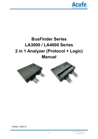 Acute BusFinder LA3000/LA4000 2 in 1 AnalyzerOfficial user manual for the BusFinder LA3000/LA4000 2 in 1 Analyzer, version 2024/12.Covers installation, probe options, software setup, and protocol...
Questions and Answers
-
What Is the Acute Technology LA3000 Plus Series Logic Analyser?
The LA3000 Plus is a PC-based logic analyser from Acute Technology Inc. for analysing digital signals and protocols in electronic systems. Its features include:
- 68/136 channels
- USB 3.0 interface
- 2.4GHz timing analysis and 300MHz state analysis
- 32Gb memory
- active probe
- logic, state and protocol triggers
- over 100 bus decodes
It runs on Windows 7, Windows 8, Windows 10 (64-bit) and Windows 11. The PC needs a USB 3.0 port and at least 8GB RAM (16GB recommended).
-
How Many Channels Does the LA3000 Plus Have?
The LA3000 Plus logic analyser has 68 or 136 channels, depending on the model (LA3068: 68, LA3136: 136).
-
Can I Set a Trigger on a Bus Protocol State?
Yes. The LA3000 Plus supports Bus Trigger I (I²C, MIPI I3C 1.1, SPI, UART (RS232), USB PD 3 and others) and, on B+ models, Bus Trigger II (eMMC 5.0, eSPI, NAND Flash, SD 3.0, Serial Flash, SVID and others), so you can capture specific events or conditions on the bus.
-
Which Communication Protocols Does the LA4000 Support?
The LA4000 series decodes over 100 protocols. These include I²C, SPI, CAN 2.0B/CAN FD and USB PD 3, plus high-speed protocols such as eMMC 5.1 and NAND Flash. For custom or proprietary protocols, Acute offers a Protocol Decode SDK for writing your own decoder DLLs.
-
Can the LA4000 Be Integrated with Other Test Instruments?
Yes. The LA4000 series stacks with oscilloscopes from Acute, GW Instek, Tektronix, Keysight/Agilent, LeCroy, HAMEG and R&S.
Link the trigger ports with the BNC-MCX cable and connect the oscilloscope to the PC over USB or LAN; the pair then works as a mixed-signal oscilloscope (MSO) with synchronised digital and analogue signals.
-
What Are the PC System Requirements for the LA4000?
The LA4000 needs a PC with:
- Windows 7, 8, 10 or 11 (64-bit versions only)
- a USB 3.0 port
- at least 8GB RAM (16GB recommended)
-
Why Should I Choose the LA4000 Logic Analyser?
The Acute Technology LA4000 combines high performance, broad protocol support and DSO integration in one compact unit:
- Sampling: timing analysis up to 4GHz for fast signals.
- Channels: 68 or 136, covering embedded platforms through to complex FPGAs.
- Memory: 32Gb capture memory for long-duration or high-density captures.
- Protocols: over 100 decoders, including I²C, SPI, CAN, eMMC 5.1 and USB PD 3, plus your own decoders via Acute's Protocol Decode SDK.
- Inputs: ±15V input range, tolerates up to ±40V, with 10mV trigger voltage steps.
- DSO stacking: combines with Keysight, Tektronix, R&S and other supported oscilloscopes to form a mixed-signal oscilloscope (MSO).
- Connection: USB 3.0 to the PC.
- Software: PC software and drivers downloadable from Acute's website.
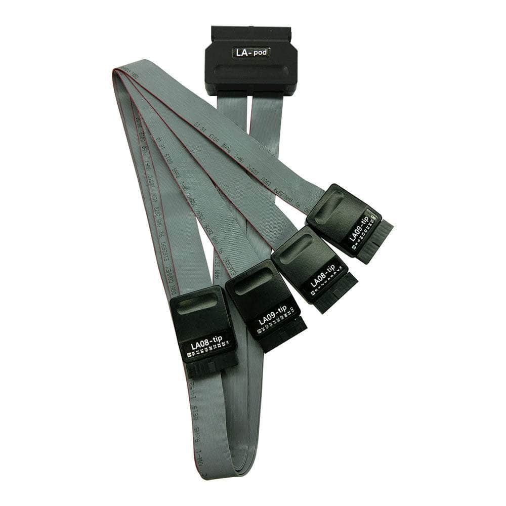
- Accessories: ships with pods, grippers and cables.
-
What Are the Key Performance Specifications of the LA4000 Series?
The LA4000 series is a PC-based instrument that works as both a logic analyser and a protocol analyser. Key specifications:
- Timing analysis: up to 4 GHz sampling rate
- State analysis: up to 400 MHz state clock rate
- Channels: 68 and 136-channel models
- Memory: 32Gb total
- Connectivity: USB 3.0 interface to the PC
No questions match your search.
