
SD, SDIO and eMMC Interfaces
SD cards, SDIO modules and eMMC chips share one bus design: a host-driven clock, a command line that carries 48-bit commands and the card's responses, and one, four or eight data lines that move blocks protected by CRCs. To capture the bus, use a card breakout board such as the ZeroPlus microSD breakout to give a logic analyser with an SD or eMMC decoder access to the bus lines.
How the Bus Is Wired
The host always drives CLK. CMD is bidirectional. SD cards drive it push-pull; eMMC uses open drain during identification, then push-pull. The data lines are bidirectional; a host may use one line (1-bit mode) or four, and eMMC adds DAT4 to DAT7 and a data strobe for the fastest modes. SD cards also support a separate SPI mode, which many microcontrollers use because it needs only an SPI port; the commands are similar but responses and CRC handling differ.
How Commands and Data Move
- Identification at low speed: the host starts CLK at 400 kHz or less and sends CMD0 (reset), CMD8 (voltage check, SD 2.0 and later), then repeats ACMD41 until the card reports it is ready. eMMC uses CMD1 instead of ACMD41.
- Addressing: CMD2 reads the card identification register (CID), and CMD3 sets the relative card address (RCA): an SD card proposes its own, while an eMMC host assigns one. CMD7 selects the card for data transfer.
- Speed up: the host sets the bus width (ACMD6 for SD, a SWITCH command for eMMC) and switches speed mode with CMD6, then raises CLK.
- Read and write: CMD17 or CMD18 reads one or many blocks; CMD24 or CMD25 writes. Each data block on each line ends with a CRC16, and the card signals busy by holding DAT0 low while it programs.
- SDIO: I/O cards use CMD52 for single register access and CMD53 for block transfers to their functions, and can raise an interrupt on DAT1.
Speed Modes
| Mode | Clock | Bus | Peak Rate | Signalling |
|---|---|---|---|---|
| SD Default Speed | Up to 25 MHz | 4-bit | 12.5 MB/s | 3.3 V |
| SD High Speed | Up to 50 MHz | 4-bit | 25 MB/s | 3.3 V |
| SD UHS-I SDR104 | Up to 208 MHz | 4-bit | 104 MB/s | 1.8 V |
| eMMC High Speed | Up to 52 MHz | 8-bit | 52 MB/s (SDR) | 3.3 V or 1.8 V |
| eMMC HS200 | Up to 200 MHz | 8-bit | 200 MB/s | 1.8 V or 1.2 V |
| eMMC HS400 | Up to 200 MHz, DDR | 8-bit | 400 MB/s | 1.8 V or 1.2 V, with data strobe |
UHS-I cards start at 3.3 V and switch to 1.8 V signalling with CMD11; a host that cannot switch stays in High Speed. UHS-II and SD Express use separate high-speed differential lanes or PCIe and are outside what a logic analyser can decode. For the fast modes, the host also runs a tuning sequence (CMD19 for SD, CMD21 for eMMC) to find the best sampling point.
Where SD, SDIO and eMMC Are Used
- Removable storage: SD and microSD in cameras, data loggers, single-board computers and instruments.
- Embedded storage: eMMC as the boot and file system device in phones, tablets, set-top boxes, industrial controllers and vehicles.
- Wireless modules: Wi-Fi and Bluetooth combo modules connected over SDIO.
- Booting: many processors boot directly from SD or from an eMMC boot partition, so the first commands after reset decide whether a board starts.
Common SD and eMMC Faults and How to Find Them
| Symptom | Likely Cause | What to Check |
|---|---|---|
| Card not detected | No response to CMD0 or CMD8, or ACMD41 never reports ready | Decode the start-up commands and the card's responses; check card supply and pull-ups on CMD and DAT |
| Works in High Speed, fails in UHS-I | Voltage switch to 1.8 V not completed, or tuning failed | Capture CMD11 and the tuning commands, and measure the I/O voltage |
| Random CRC errors on reads | Signal integrity at the chosen clock rate, or a long probe disturbing the bus | Compare errors at a lower clock; shorten ground leads; look at edges on an oscilloscope |
| Writes hang | Host does not wait while the card holds DAT0 low (busy) | Measure the busy period after each write block |
| Board does not boot from eMMC | Boot partition or boot configuration bytes in EXT_CSD not set | Decode the boot sequence and the SWITCH commands that set the partition |
| Wi-Fi module drops off the SDIO bus | Interrupt on DAT1 missed, or the host clock gated during a transfer | Capture CMD53 traffic and DAT1 together |
Tools for Analysing and Decoding SD, SDIO and eMMC
Watch tools capture the bus and decode commands, responses and data blocks. Sample at four or more times CLK: 100 MS/s covers Default Speed, while High Speed needs 200 MS/s or more. For HS200, HS400 and SDR104, a logic analyser can capture the slow identification phase, but you will usually need to lower the clock to decode data reliably.
Logic Analysers With SD and eMMC Decoding
| Product | Role | Capability | Price ex VAT |
|---|---|---|---|
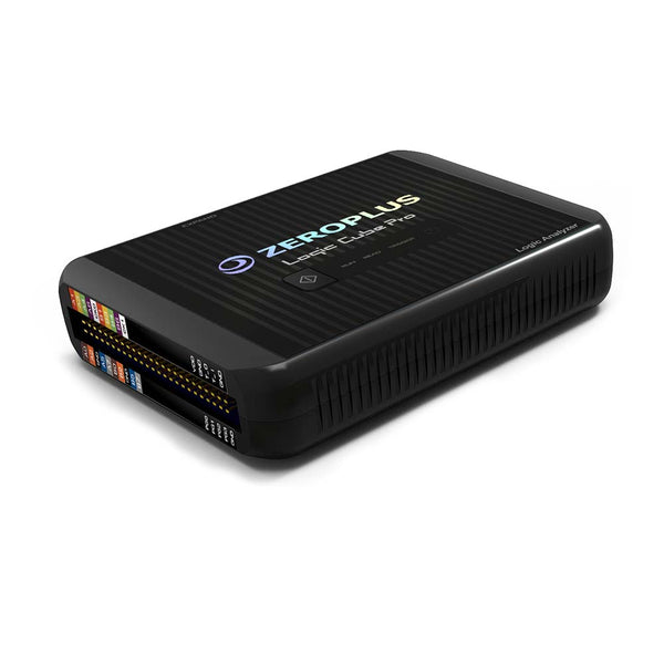
| ZeroPlus LAP-C Pro Series | Watch | Logic analyser with SD 2.0/SDIO protocol analysis (eMMC decoding needs the LAP-F series) | £925 |
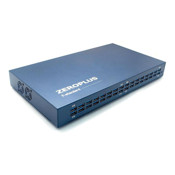
| ZeroPlus LAP-F 40/64-Channel | Watch | 40 or 64 channels; adds eMMC 5.1 (CLK, CMD, DAT0 to DAT7 and data strobe) and SD 3.0 decoding; full-speed eMMC and SD 3.0 decoding on 32 channels is an optional upgrade | £1,350 |
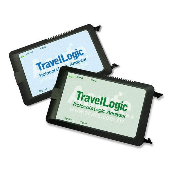
| Acute TravelLogic 34-Channel | Watch | Logic analyser running Acute's decoder library, which includes SD/SDIO and eMMC/MMC | £1,161.65 |
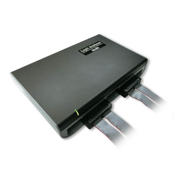
| Acute LA4000 Series | Watch | Up to 136 channels at higher sample rates for fast eMMC and system-level captures; same decoder library | £7,100 |
Card Breakout Boards
| Product | Role | Capability | Price ex VAT |
|---|---|---|---|
| ZeroPlus Standard SD Card Breakout Board | Card breakout board for full-size SD, for connecting a logic analyser to the SD bus | £29.15 | |
| ZeroPlus MicroSD Card Breakout Board | The same for microSD | £37.50 | |
| ZeroPlus MiniSD Card Breakout Board | The same for miniSD | £37.50 |
If your design talks to the card in SPI mode, see our SPI protocol guide for SPI analysers. Working with soldered eMMC and need a probe point? Tell us the package and speed mode and we will suggest a way in.
Frequently Asked Questions
What Is the Difference Between SD Mode and SPI Mode?
SD mode uses CMD and up to four data lines with CRCs on everything and supports the fast speed modes. SPI mode uses a standard SPI port, one data line each way, with CRC optional, and is limited to lower speeds. SPI mode is simpler to implement on a small microcontroller; SD mode is needed for performance.
Is eMMC the Same as an SD Card?
They share the command structure, but eMMC is a soldered-down MultiMediaCard with up to eight data lines, boot partitions, a different initialisation command (CMD1) and its own speed modes up to HS400. An SD decoder will follow much of an eMMC capture but may misread eMMC-specific commands, so use an eMMC decoder where available.
Can a Logic Analyser Capture UHS-I or HS400?
Capturing the start-up and tuning is practical. Decoding data at 200 MHz or in DDR needs sample rates and probing beyond most PC-based logic analysers. The usual approach is to capture at a lower forced clock rate, or capture the slower phases where most bring-up problems happen.
What Does SDIO Add?
SDIO lets non-storage devices, mainly Wi-Fi and Bluetooth modules, use the SD bus. It adds commands for register and block access to I/O functions (CMD52 and CMD53) and an interrupt signal on DAT1. The physical bus and speed modes are the same as SD.
Why Use a Breakout Board?
SD and microSD contacts are hidden inside the socket. A card breakout board brings the bus out to pins for analyser leads, so you do not need to solder to the target.
Where to Start with SD, SDIO and eMMC
More Protocols
By John Legg CEng, Director, Debug Store. Updated 12 November 2026.
