


SEGGER Microcontroller GmbH
SEGGER 0.1" To 50-mil 10-Pin Patch Adapter
SEGGER 0.1" To 50-mil 10-Pin Patch Adapter
SKU: 8.06.28
Couldn't load pickup availability
Key Features
Overview
Downloads
Why Engineers Choose The SEGGER 0.1" To 50-mil 10-Pin Patch Adapter
Space Optimisation
Legacy Support
Cost Efficiency
Technical Overview
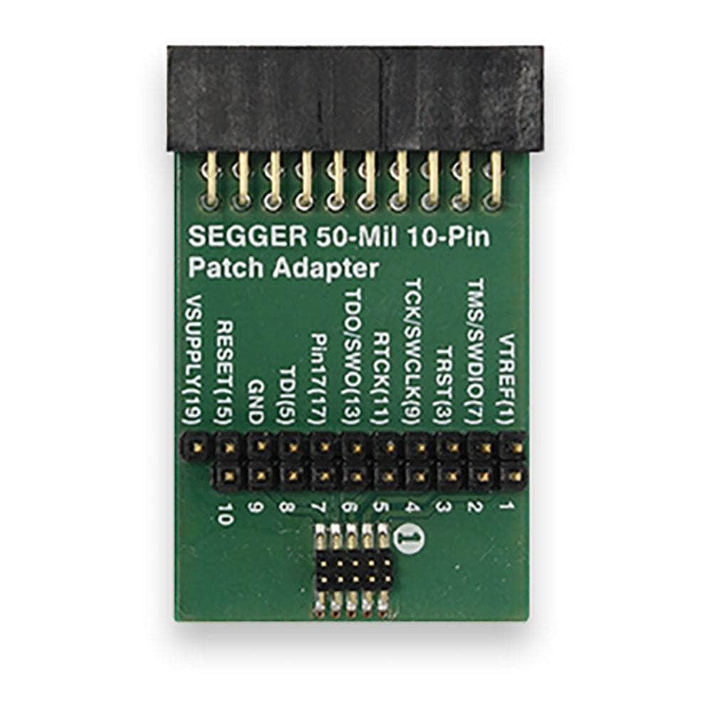
The SEGGER 50-Mil 10-Pin Patch Adapter bridges the gap between traditional 20-pin JTAG interfaces and modern compact 10-pin Cortex-M connectors. This professional-grade adapter serves dual purposes: standard Cortex-M connectivity and custom pin mapping for legacy or proprietary designs.
Connector Specifications
| Side | Connector Type | Pin Count | Pitch | Compatible With |
|---|---|---|---|---|
| Input | 20-pin IDC Socket | 20 | 0.1" (2.54mm) | Standard JTAG debuggers |
| Output | 10-pin Header | 10 | 0.05" (1.27mm) | ARM Cortex-M targets |
Standard Cortex-M Pinout
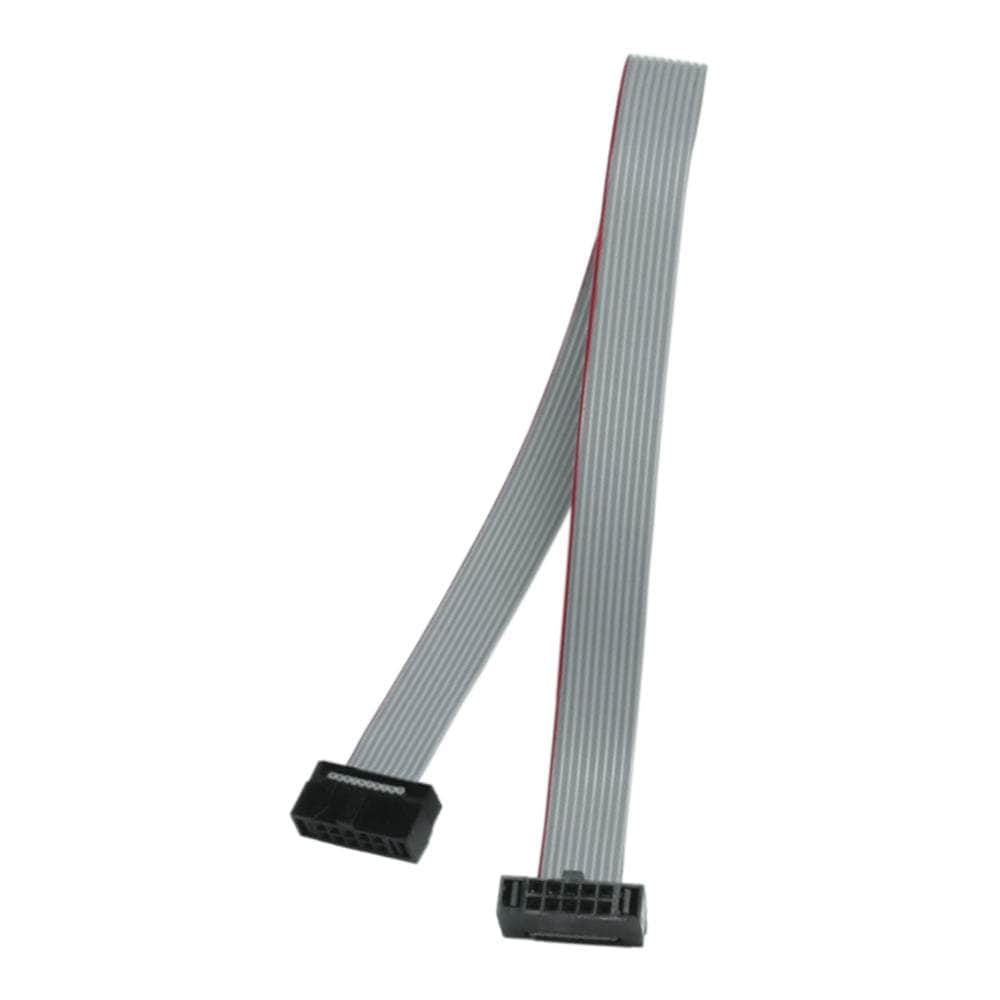
When used with the included ribbon cable, the adapter follows ARM's standard 10-pin Cortex-M debug connector specification:
| Pin | Signal | Pin | Signal |
|---|---|---|---|
| 1 | VTref | 2 | SWDIO/TMS |
| 3 | GND | 4 | SWCLK/TCK |
| 5 | GND | 6 | SWO/TDO |
| 7 | KEY (No pin) | 8 | NC/TDI |
| 9 | GND | 10 | nRESET |
Custom Wiring Quick-Start
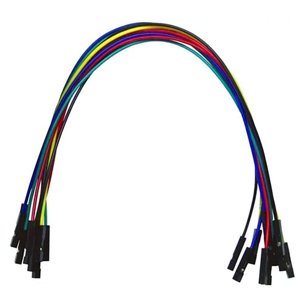
For non-standard pinouts, replace the ribbon cable with individual jumper wires:
- Disconnect the ribbon cable from the 10-pin header side
- Identify target pinout from your PCB documentation
- Connect jumper wires between 20-pin test points and 10-pin header pins
- Verify connections with multimeter before powering target
Compatible Debug Probes
This adapter works with any debug probe featuring a standard 20-pin 0.1" JTAG connector:
- SEGGER: J-Link BASE, PLUS, PRO, ULTRA+, WiFi, Flasher series
- STMicroelectronics: ST-LINK/V2, ST-LINK/V3SET
- P&E Micro: Multilink Universal, Cyclone ARM
- ARM: ULINK2, ULINKplus (with adapter)
PCB Layout Considerations
When designing PCBs for 10-pin debug connectors:
| Parameter | Recommendation | Notes |
|---|---|---|
| Connector Type | Samtec FTSH-105-01-L-DV | Shrouded, surface mount |
| Keep-out Zone | 3mm all sides | For connector and cable clearance |
| Via Size | 0.2mm drill min | Standard PCB manufacturing |
| Trace Width | 0.1mm minimum | For high-speed signals |
Signal Integrity Guidelines
For reliable high-speed debugging:
- Cable Length: Keep total cable length under 30cm
- Ground Planes: Use solid ground planes under debug traces
- Impedance: Match 50Ω characteristic impedance for clock signals
- Termination: Add series termination resistors if signal integrity issues occur
Troubleshooting Common Issues
| Symptom | Possible Cause | Solution |
|---|---|---|
| No target detection | VTref not connected | Verify pin 1 connection to target VCC |
| Intermittent connection | Poor jumper wire contact | Check all jumper wire connections |
| High-speed programming fails | Cable too long | Reduce total cable length |
| Cannot reset target | nRESET not connected | Connect pin 10 to target reset |
Application Examples
Space-Constrained IoT Devices
Modern IoT devices often cannot accommodate 20-pin connectors. This adapter enables the use of compact 10-pin connectors while maintaining compatibility with existing JTAG tools.
Legacy System Integration
When working with older designs that use non-standard debug pinouts, the custom wiring capability allows connection without PCB modifications.
Production Programming
In manufacturing environments, the compact connector reduces fixture complexity while maintaining programming speed and reliability.
| General Information | |
|---|---|
Product Type |
Adapter
|
Part Number (SKU) |
8.06.28
|
Manufacturer |
|
| Physical and Mechanical | |
Weight |
0.02 kg
|
| Other | |
EAN |
5055383614400
|
Questions and Answers
-
What's the Maximum Cable Length I Can Use with This Adapter?
SEGGER does not publish a maximum cable length for this adapter. As general guidance, keep the cable between the adapter and the target as short as practical for reliable high-speed debugging.
-
Can This Adapter Handle 3.3V and 5V Target Voltages?
The adapter is passive and voltage-transparent, so it works with any target voltage your debug probe supports. Check your probe's VTref range for 1.8V or 5V targets. Most modern applications use 3.3V.
-
Does This Work with Automotive-Grade Debugging Applications?
Yes. It is a passive adapter, so it can be used on automotive targets in the same way as any other target.
-
What Connectors Are Compatible on the Target Side?
The 10-pin side uses standard 0.05" (1.27mm) pitch connectors. Compatible target connectors include Samtec FTSH series and equivalent 2x5 0.05" shrouded headers.
-
How Does This Compare to Tag-Connect Solutions for Space-Saving?
Tag-Connect footprints use spring pins and do not need a fitted connector. This adapter is used with standard 0.05" connectors on the target, which suits boards that already carry a debug header.
-
What's the Difference Between This Adapter and SEGGER's Other Cortex-M Adapters?
This patch adapter allows custom connections and wiring: it has two labelled pin-header rows that you patch with your own wire links. Standard adapters such as the 9-Pin and 19-Pin Cortex-M adapters have fixed pinouts. The patch adapter works with both standard Cortex-M and non-standard designs.
-
Can I Use This Adapter with Non-SEGGER Debug Probes?
SEGGER lists J-Link models as suitable products and also carries the adapter in its Flasher adapter range. The 20-pin side follows the standard Arm 20-pin layout, so check a third-party probe's pinout against it before connecting.
-
What's Included in the Package?
SEGGER lists the adapter board only. The two labelled header rows are patched with your own wire links, and a 10-pin 0.05" cable to the target is needed.
-
How Do I Wire Custom Pinouts with This Adapter?
Use your own wire links between the two labelled header rows to match your target's pinout. The adapter has clearly marked connection points on both the 20-pin and 10-pin sides.
-
Is This Compatible with SWD (Serial Wire Debug) Interface?
Yes, the adapter supports both JTAG and SWD with compatible debug probes. SWD needs only 4 connections: VCC, GND, SWCLK and SWDIO.


No questions match your search.