
USB Power Delivery Protocol
USB Power Delivery (PD) lets a USB-C charger and a device agree on a voltage and current above the 5 V default, up to 20 V and 100 W, or 48 V and 240 W with Extended Power Range. The negotiation runs as packets on the CC (configuration channel) wire, separate from the USB data lines. To see why a device charges slowly or not at all, capture the CC line with a logic analyser or oscilloscope that has a USB PD decoder, alongside VBUS.
How USB-C Attaches Before PD Starts
A USB-C source presents a pull-up (Rp) on CC, and a sink a 5.1 kΩ pull-down (Rd). The resulting voltage tells the sink that something is attached, which way up the plug is, and whether the source offers default USB current, 1.5 A or 3 A at 5 V. Only then does the source turn on VBUS. PD is optional on top of this: a device that never sends a PD message still gets 5 V.
How a PD Contract Is Negotiated
- Capabilities: the source sends Source_Capabilities, a list of power data objects (PDOs): fixed voltages such as 5, 9, 15 and 20 V with a maximum current, and on newer chargers programmable (PPS) or adjustable (AVS) ranges.
- Request: the sink picks one PDO by its position in the list and states the current it needs.
- Accept and transition: the source accepts (or sends Reject or Wait), changes VBUS, then sends PS_RDY. From then on that is the explicit contract.
- Acknowledge: every message is answered with GoodCRC within a short time; a missing GoodCRC makes the sender retry.
- More: later messages renegotiate power, swap power or data roles, query the cable's e-marker (sent as SOP' packets) and enter alternate modes such as DisplayPort through structured vendor-defined messages.
On the Wire
PD packets use biphase mark coding at about 300 kbit/s, riding on the DC level already on CC. Each packet has a preamble, a start-of-packet ordered set (SOP for the partner, SOP' and SOP'' for the cable), a 16-bit header, data objects, a CRC-32 and an end-of-packet symbol, with data in 4b5b code. Because the signal swing is about 1.1 V on top of a DC level set by Rp and Rd, and the other CC pin may carry VCONN at about 5 V, set the logic analyser threshold carefully or capture it as an analogue signal.
Power Ranges
| Range | Voltages | Maximum Power | Notes |
|---|---|---|---|
| USB Type-C current | 5 V | 15 W (3 A) | Advertised by Rp, no PD messages needed |
| Standard Power Range (SPR) | 5, 9, 15, 20 V fixed; PPS up to 21 V (from 3.3 V in PD 3.0, from 5 V in current revisions) | 100 W (5 A at 20 V) | Above 3 A needs a 5 A e-marked cable |
| Extended Power Range (EPR, PD 3.1) | 28, 36, 48 V fixed; AVS 15 to 48 V | 240 W (5 A at 48 V) | Needs an EPR-capable source, sink and cable |
Where USB PD Is Used
- Chargers and power banks: one adapter powering phones, tablets and laptops at the right voltage.
- Laptops and docks: power, data and DisplayPort over one cable, with role swaps between dock and laptop.
- Embedded products: boards that take 9, 15 or 20 V from any USB-C charger through a PD sink controller, replacing barrel jacks.
- Higher-power devices: EPR at 28 V to 48 V for products that need more than 100 W.
Common USB PD Faults and How to Find Them
| Symptom | Likely Cause | What to Check |
|---|---|---|
| Device stays at 5 V | No PD messages sent, or the sink never answered Source_Capabilities | Capture CC after attach: look for Source_Capabilities and a GoodCRC from the sink |
| Negotiation repeats in a loop | GoodCRC missing or late, so the sender retries and resets | Measure the gap between each message and its GoodCRC |
| 20 V offered, sink only gets 3 A | Cable not e-marked for 5 A | Look for the SOP' Discover Identity exchange with the cable |
| Hard reset during charging | Sink draws more than the contract, or a protocol timeout expired | Capture VBUS current with the CC traffic and look for Hard_Reset |
| Works with one charger, not another | Sink requests a PDO position or PPS range that charger does not offer | Compare the two chargers' Source_Capabilities |
| External display does not start over USB-C | Alternate mode discovery or Enter Mode failed | Decode the structured VDMs: Discover SVIDs, Discover Modes, Enter Mode |
Tools for Analysing USB Power Delivery
Watch tools capture CC traffic between a real source and sink, using a USB-C breakout or test fixture to reach CC1, CC2 and VBUS.
Logic Analysers With USB PD Decoding
| Product | Role | Capability | Price ex VAT |
|---|---|---|---|
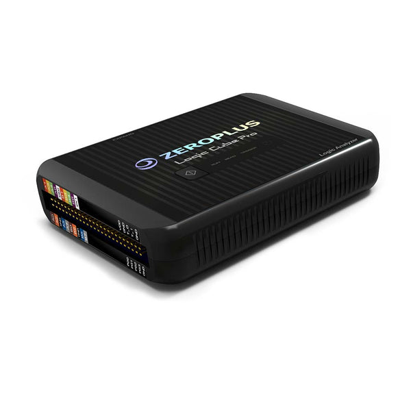
| ZeroPlus LAP-C Pro Series | Watch | Logic analyser with USB PD 3.0 protocol analysis | £925 |
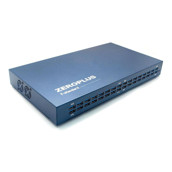
| ZeroPlus LAP-F 40/64-Channel | Watch | 40 or 64 channels with the same USB PD 3.0 decoder | £1,350 |
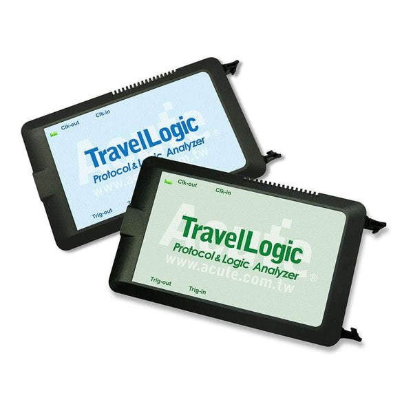
| Acute TravelLogic 34-Channel | Watch | Logic analyser running Acute's decoder library, which includes USB PD 3.1; the UFCS fast-charging decoder is supplied on request from Acute | £1,161.65 |
Measuring VBUS Alongside USB Data
| Product | Role | Capability | Price ex VAT |
|---|---|---|---|
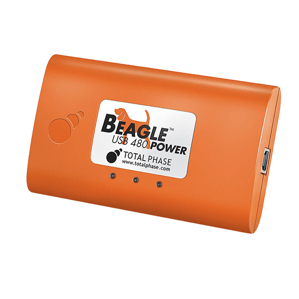
| Total Phase Beagle USB 480 Power Protocol Analyser, Ultimate Edition | Watch | Captures USB 2.0 traffic with VBUS current and voltage measurement on the same timeline, through USB Type-A and Type-B ports; it cannot sit on a USB-C to USB-C link and does not decode PD messages | £2,680 |
For the USB data protocol itself, see our USB 2.0 and USB 3 guides. Tell us your PD version and power range and we will recommend a capture set-up.
Frequently Asked Questions
Is USB PD the Same as USB-C?
No. USB-C is the connector and cable standard, including the CC line and the basic 5 V current levels. USB PD is an optional protocol that runs over the CC line to negotiate higher voltages and power. Many USB-C devices never use PD.
What Is PPS?
Programmable Power Supply, added in PD 3.0. The sink requests a voltage within a range in 20 mV steps, and a current limit, and can adjust it every few seconds. Phones use it to charge the battery directly with less heat in the phone.
Do I Need a Special Cable for 100 W?
Yes. Above 3 A the cable must contain an electronic marker (e-marker) chip that reports 5 A capability, and the source checks it over SOP' messages before offering 5 A. EPR at up to 240 W needs an EPR-rated e-marked cable.
Can a Logic Analyser Capture PD Messages?
Yes, with a USB PD decoder and care with the threshold: the PD signal is a small swing on top of a DC level on CC. Capture CC1 and CC2, because only one carries PD depending on plug orientation.
Why Does My Board Only Get 5 V From a PD Charger?
A PD charger supplies 5 V until a sink negotiates more. Your board needs a PD sink controller, or firmware on a PD-capable controller, to read Source_Capabilities and request a higher voltage.
Where to Start with USB Power Delivery
More Protocols
By John Legg CEng, Director, Debug Store. Updated 12 November 2026.
