


Tag-Connect, LLC
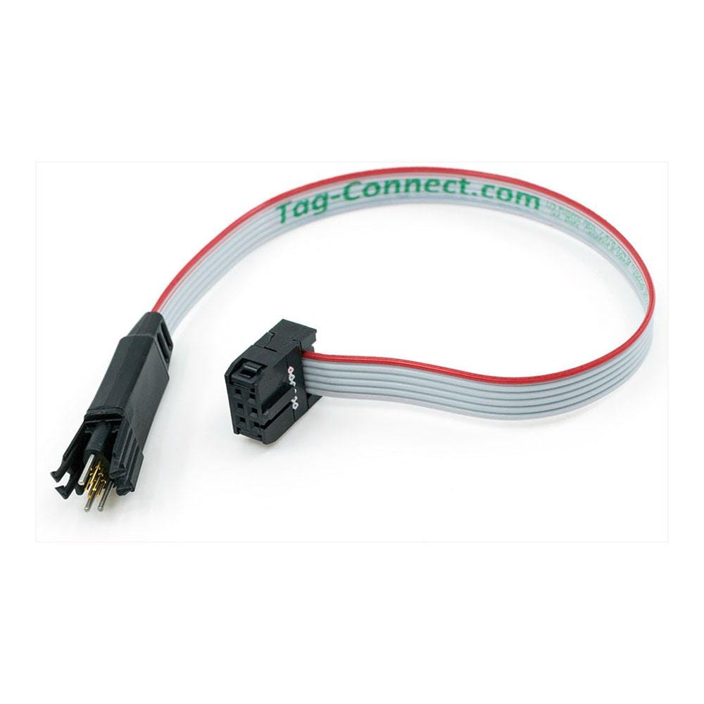
Tag Connect TC2030-IDC Cable
Tag Connect TC2030-IDC Cable
SKU: TC2030-IDC
Couldn't load pickup availability

Key Features
Overview
Compatible with ARM SWD, AVR ISP, and multiple debugging protocols, the standard TC2030-IDC supports popular microcontrollers from STM32, Atmel, Renesas, and Zilog families.
Engineering teams worldwide rely on this standard legged version for both development debugging and high-volume production programming where secure mechanical connection is essential. The robust design withstands over 100,000 connection cycles whilst the standardised pinout ensures compatibility across diverse embedded platforms. For applications requiring even smaller footprints or hand-held programming, the TC2030-IDC-NL no-legs version is available as an optional variant. Extended length options include the TC2030-IDC-10 for complex setups. Professional adapters connect seamlessly to industry-standard debuggers including ARM20-CTX configurations.Downloads
Professional Microcontroller Programming Made Simple
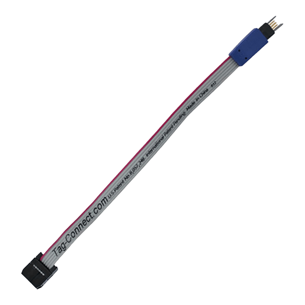
The Tag-Connect TC2030-IDC represents a breakthrough in embedded systems programming, delivering professional-grade connectivity without the bulk and cost of traditional headers. This standard 6-pin Plug-of-Nails™ cable with integrated retention legs transforms how engineers approach in-circuit programming and debugging.
Wiring Quick-Start
The TC2030-IDC features a standardised 6-pin configuration compatible with ARM SWD, AVR ISP, and multiple debugging protocols:
| Pin | Function | ARM SWD | AVR ISP |
|---|---|---|---|
| 1 | VTref/VCC | Target Voltage | VCC |
| 2 | SWDIO/MISO | Data I/O | Master In |
| 3 | GND | Ground | Ground |
| 4 | SWCLK/SCK | Clock | Serial Clock |
| 5 | GND | Ground | Ground |
| 6 | SWO/RESET | Serial Wire Output | Reset |
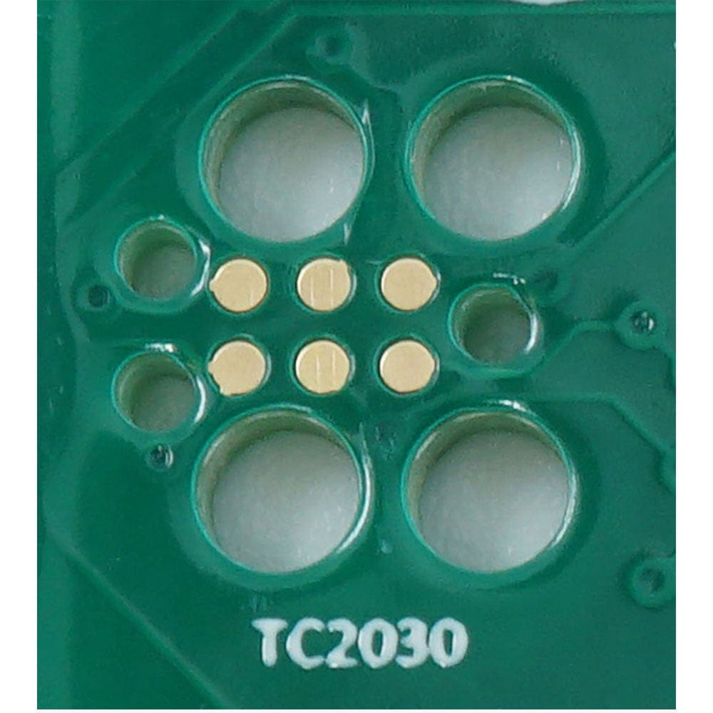
PCB Footprint Requirements: The standard TC2030-IDC requires a PCB footprint of 0.24" × 0.1" (6.1mm × 2.5mm) including alignment and latch holes for the retention legs. No solder paste should be applied to contact pads.
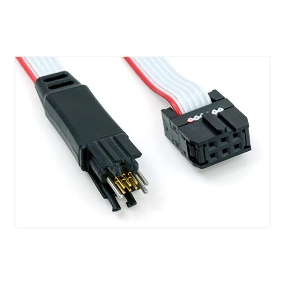
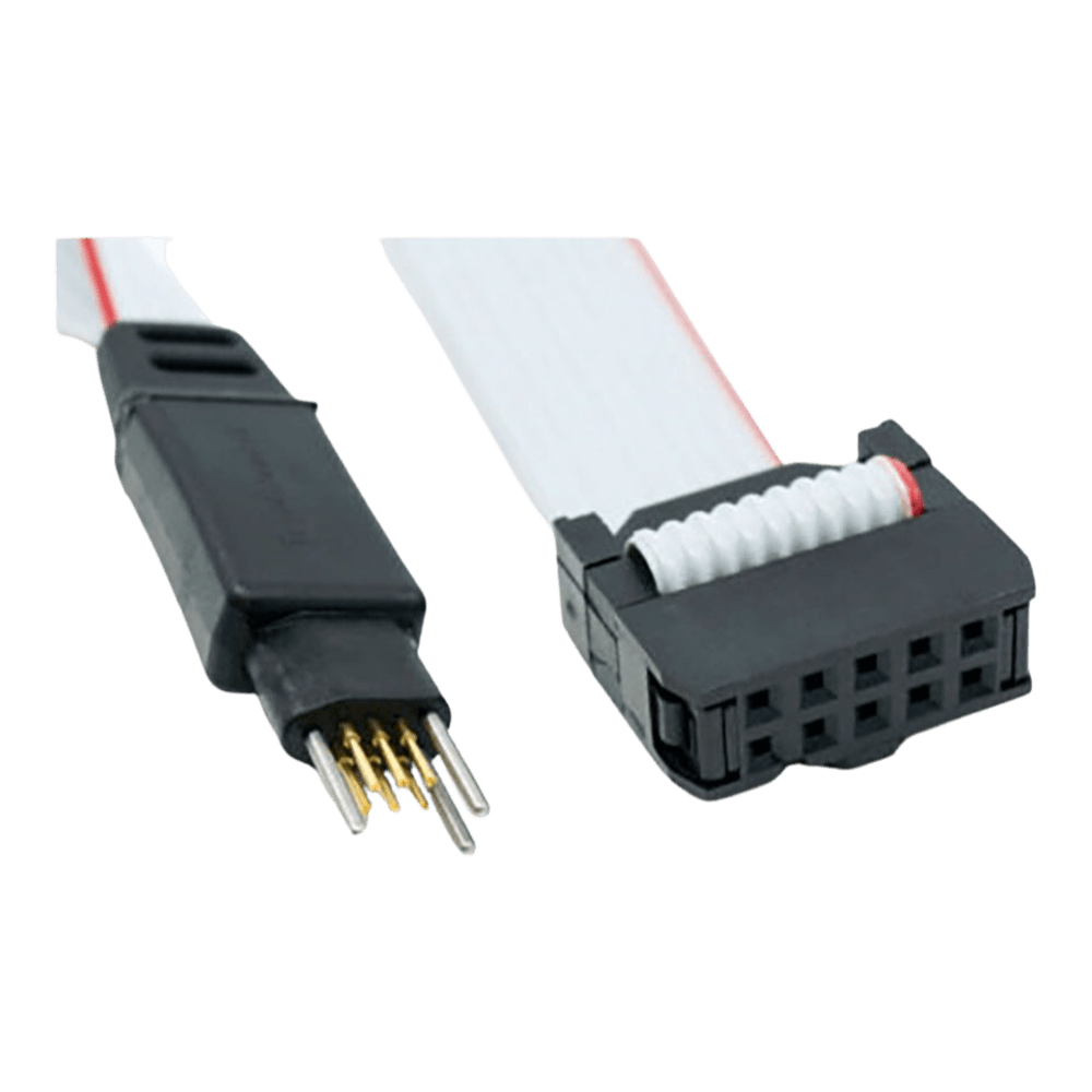
Spring-Pin Technology with Retention Legs
Each TC2030-IDC cable incorporates six high-reliability pogo spring pins rated for over 100,000 insertion cycles. The precision-manufactured pins ensure consistent electrical contact whilst the integrated plastic retention legs provide secure mechanical attachment during programming or debugging sessions—eliminating the need for programming fixtures or manual pressure.
// Example STM32 SWD connection verification if (SWD_Connect() == SWD_OK) { uint32_t device_id = SWD_ReadID(); printf("Connected to device: 0x%08X\n", device_id); } Professional Manufacturing Benefits
By eliminating header connectors, the TC2030-IDC reduces per-board costs by £2-5 whilst freeing valuable PCB real estate. The standard legged design maintains secure connection throughout production programming cycles, supporting manufacturing speeds up to 1000 units per hour without programming fixtures.
Industry Compatibility: Works seamlessly with SEGGER J-Link, ST-Link, Atmel ICE, and over 50 professional debugger platforms via appropriate adapters.
| General Information | |
|---|---|
Part Number (SKU) |
TC2030-IDC
|
Manufacturer |
|
| Physical and Mechanical | |
Weight |
0.1 kg
|
| Other | |
EAN |
5055383690893
|
Frequently Asked Questions
Have a Question?
-
How does the standard TC2030-IDC compare to traditional JTAG connectors for cost savings?
Eliminating 20-pin JTAG headers saves £3-8 per board in connector and assembly costs. Over 10,000 unit production runs, this represents £30,000-80,000 savings whilst reducing PCB complexity and improving electromagnetic compatibility through the smaller footprint.
-
Can multiple TC2030-IDC footprints be placed on one PCB?
Yes, multiple standard footprints enable programming different MCUs or accessing various debug interfaces. Ensure adequate spacing for leg operation and consider using different pin assignments to avoid signal conflicts during simultaneous connections.
-
What cable length options are available for the TC2030-IDC?
Standard length is 6 inches (152mm). The https://thedebugstore.com/products/tag-connect-tc2030-idc-10 variant provides 10 inches (254mm) for applications requiring extended reach between debugger and target hardware.
-
Does the TC2030-IDC provide target power to the connected device?
Pin 1 carries target voltage reference (VTref) which can source limited current for low-power debugging. For full target powering, use debuggers with 3.3V/5V supply capability connected through appropriate adapters with power jumper configurations.
-
How do I design the PCB footprint for a reliable connection?
The standard footprint requires six contact pads (0.025" diameter) and four alignment/latch holes for the retention legs. Critical design rules include no solder paste on contact pads, 0.02" keep-out areas around pads, and finger access clearance for leg operation.
-
What's the difference between standard TC2030-IDC and TC2030-IDC-NL versions?
The standard TC2030-IDC features retention legs that clip into PCB holes for secure debugging sessions without manual pressure. The optional TC2030-IDC-NL "no legs" version offers an even smaller footprint for quick programming operations requiring manual pressure during connection.
-
Can the TC2030-IDC handle production programming volumes?
Yes, the spring-loaded pogo pins are rated for 100,000+ insertion cycles. The standard retention legs provide secure mechanical connection enabling automated programming systems to achieve speeds up to 1000 units per hour without external programming fixtures.
-
What debuggers are compatible with the TC2030-IDC cable?
Compatible debuggers include SEGGER J-Link, ST-Link V2/V3, Atmel ICE, PEmicro Multilink, and over 50 professional platforms. Most connections require appropriate adapters such as the ARM20-CTX.
-
How does the PCB footprint compare to traditional programming headers?
The standard TC2030-IDC requires only 0.02 square inches compared to 0.15+ square inches for traditional headers. This 85% space reduction enables programming access in space-constrained designs whilst eliminating per-board connector costs of £2-5.
-
What microcontroller families does the TC2030-IDC support?
The standard TC2030-IDC supports ARM Cortex (STM32, NXP, Nordic), Atmel AVR, Renesas MCUs, and Zilog processors. The standardised 6-pin configuration accommodates SWD, JTAG, ISP, and proprietary debug protocols through appropriate adapter connections.