
MIPI RFFE and SPMI Interfaces
MIPI RFFE (RF Front-End Control Interface) is the two-wire bus a phone's modem uses to configure its power amplifiers, antenna switches, filters and tuners, with tight timing so settings change exactly at slot boundaries. MIPI SPMI (System Power Management Interface) is the related two-wire bus between an application processor and its power management ICs. Both use push-pull clock and data with their own frame format, so they need RFFE or SPMI decoders, not I2C ones.
How RFFE Works
- Sequence start: the controller signals a start condition on SDATA while SCLK is low.
- Command frame: a 4-bit unique slave identifier (USID) and an 8-bit command with a parity bit. Register 0 Write uses a short form for the most common setting; Register Write and Read reach registers 0 to 31; Extended Register commands reach 256 registers and up to 16 bytes at a time, and Extended Register Long commands use a 16-bit address for up to 65,536 registers.
- Data frames: each byte followed by a parity bit. For reads, the target drives SDATA after a bus park cycle.
- Bus park: the controller drives SDATA low for one clock, then releases it, ending the sequence cleanly.
- Triggers: devices can hold new register values in shadow registers until a trigger write, so several devices switch at the same instant, for example at the start of a transmit slot.
How SPMI Differs
SPMI carries power management traffic between a processor (or several) and power management ICs: setting regulator voltages, reading status and handling power state changes. It allows up to four masters and 16 slaves on the bus, with arbitration to decide who sends next. RFFE v2.0 and later can also have up to four controllers, but most RFFE buses use one. Its command set covers register reads and writes, extended register access and power state commands such as reset, sleep, shutdown and wake-up.
Where RFFE and SPMI Are Used
- Phones and cellular modules: RFFE configures every front-end device for each band and power level; SPMI links the application processor and modem to their PMICs.
- Wi-Fi and IoT modules: RFFE on front-end modules with switches and amplifiers.
- Automotive telematics and tablets: the same cellular chipsets, buses and PMICs.
Common Faults and How to Find Them
| Symptom | Likely Cause | What to Check |
|---|---|---|
| Device ignores commands | Wrong USID, or two devices sharing one USID | Decode the USID field and compare with the device strapping or programmed ID |
| Settings change at the wrong time | Trigger not sent, or sent before the shadow register write | Decode the sequence order around the transmit slot |
| Parity errors in the decode | Signal integrity at the clock rate, or probing loading the bus | Check edges on an oscilloscope; reduce probe lead length |
| PMIC rail does not come up | SPMI write lost in arbitration or to the wrong register | Decode SPMI arbitration and register writes at power-up |
Tools for Analysing and Decoding RFFE and SPMI
Watch tools capture SCLK and SDATA and decode them into commands and data. Set the logic threshold for 1.2 V or 1.8 V signalling, and sample at four or more times the clock rate.
| Product | Role | Capability | Price ex VAT |
|---|---|---|---|
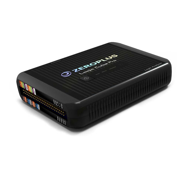
| ZeroPlus LAP-C Pro Series | Watch | Logic analyser with MIPI RFFE protocol analysis; ZeroPlus also lists a MIPI SPMI decoder | £925 |
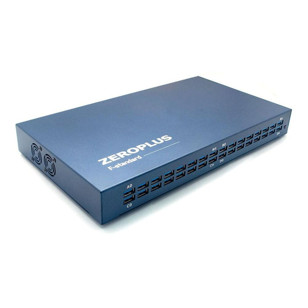
| ZeroPlus LAP-F 40/64-Channel | Watch | 40 or 64 channels; ask us to confirm MIPI RFFE and SPMI support on this model | £1,350 |
| Acute TravelLogic 34-Channel | Watch | Logic analyser running Acute's decoder library, which includes MIPI RFFE; the SPMI decoder is supplied on request from Acute | £1,161.65 |
For the MIPI sensor bus, see our I3C guide. Tell us the MIPI interface and version and we will confirm decoder support before you buy.
Frequently Asked Questions
Is RFFE the Same as I2C?
No. RFFE uses two wires, but push-pull at low voltage, with a different start condition, parity bits instead of acknowledges, a bus park cycle and trigger mechanisms. An I2C decoder cannot read it.
What Is a USID?
The Unique Slave Identifier: a 4-bit address that selects one device on an RFFE bus. Value 0 is reserved for broadcast, so up to 15 devices can be addressed individually.
What Is the Difference Between RFFE and SPMI?
RFFE controls RF front-end parts from the modem with precise timing, usually from one controller per bus. SPMI connects processors to power management ICs and allows up to four masters. Both come from the MIPI Alliance and have a similar two-wire structure.
Can I Get the RFFE Specification?
The full specifications are available to MIPI Alliance members. Device datasheets usually describe the commands they support, and decoder vendors implement the standard frame formats.
Where to Start with MIPI RFFE and SPMI

More Protocols
By John Legg CEng, Director, Debug Store. Updated 12 November 2026.
