Overview
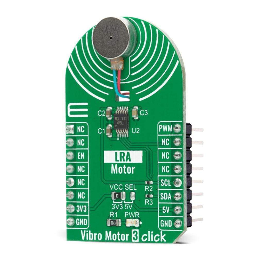
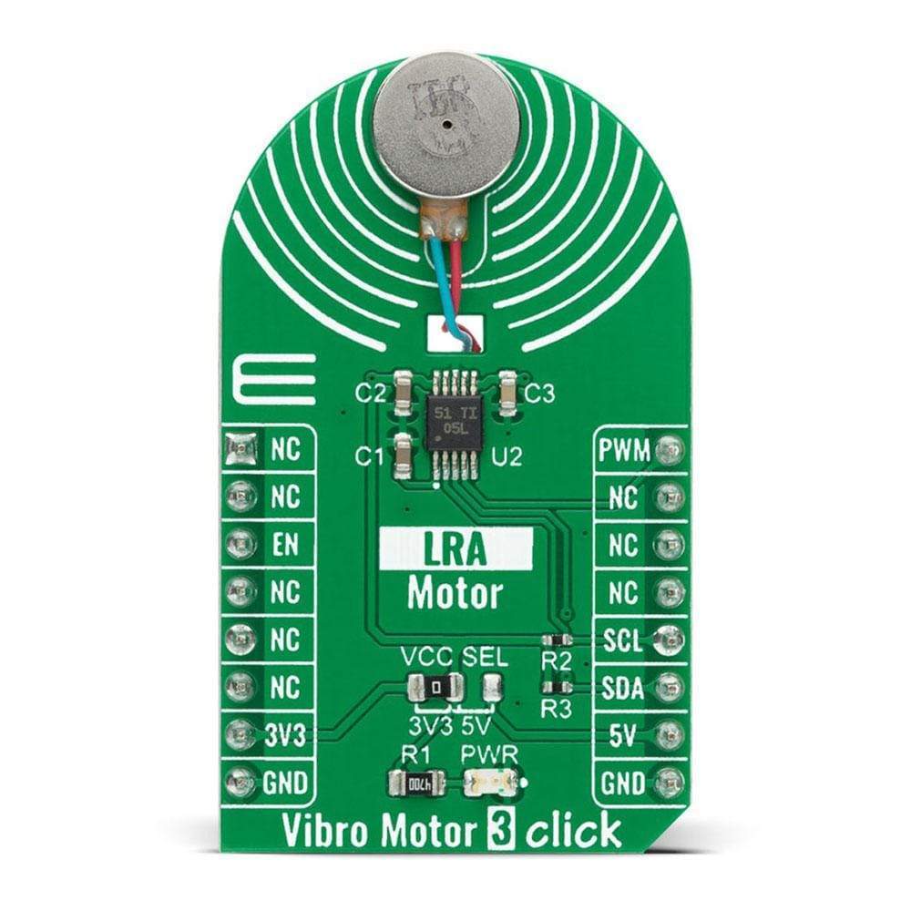
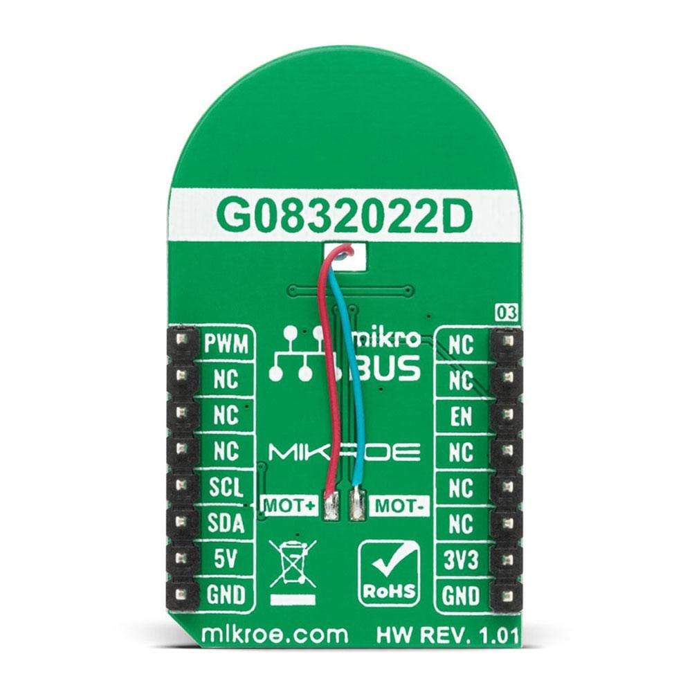
The Vibro Motor 3 Click Board™ is a compact add-on board that makes an ideal solution for adding simple haptic feedback in any design. This board features the G0832022D, a coin-sized linear resonant actuator (LRA) that generates vibration/haptic feedback in the Z plane, perpendicular to the motor's surface from Jinlong Machinery & Electronics, Inc. Driven by a flexible Haptic/Vibra driver the DRV2605, the G0832022D vibrates in the Z-axis, which is perpendicular to the face of the vibration motor. It draws only 19mA at 0.6V while producing a G force of 0.55 GRMS, making it ideal for battery-powered wearables. This Click Board™ makes an excellent choice for devices with limited battery capacity and for users where crisp haptic feedback and low power consumption are required.
Vibro Motor 3 Click is supported by a mikroSDK compliant library, which includes functions that simplify software development. This Click Board™ comes as a fully tested product, ready to be used on a system equipped with the mikroBUS™ socket.
Downloads
How Does The Vibro Motor 3 Click Board™ Work?
The Vibro Motor 3 Click Board™ is based on the G0832022D, a coin-sized linear resonant actuator that generates vibration/haptic feedback in the Z plane, perpendicular to the motor's surface from Jinlong Machinery & Electronics, Inc. The G0832022D draws only 19mA at 0.6V while producing a G force of 0.55 GRMS and makes an excellent choice for applications requiring crisp haptic feedback and low power consumption. For haptic feedback applications, fast rise and fall times are critical for achieving the optimal user experience.
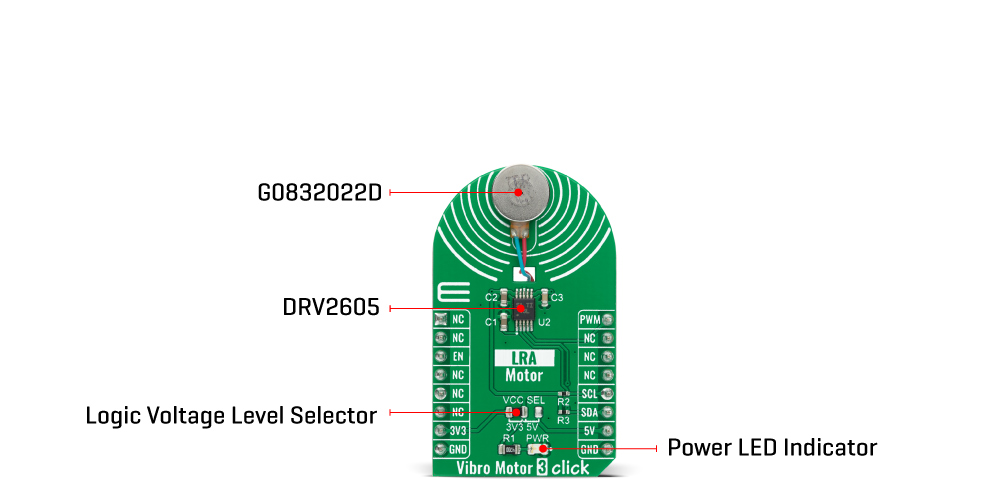
Driven by the DRV2605, a flexible Haptic/Vibra driver from Texas Instruments, this Click board™ is designed to provide extremely-flexible haptic control over a standard I2C 2-Wire interface with a maximum clock frequency of 400kHz. It possesses enabling function, routed on the CS pin of the mikroBUS™ socket labeled as the EN, and comes up with an extensive integrated library of over 100 licensed effects that eliminates the need to design haptics waveforms. It also contains a smart-loop architecture, which allows effortless auto resonant drive for LRA motor drive. This feedback provides automatic overdrive and braking, which creates a simplified input waveform paradigm as well as reliable motor control and consistent motor performance.
Additionally, the DRV2605 can also operate in the PWM Mode and accept the PWM signal from the PWM pin of the mikroBUS™ socket. In this mode, the DRV2605 device drives the actuator continuously until the user sets the DRV2605 to a Standby Mode or enters another interface mode. In PWM Mode, the strength of vibration is controlled by the duty cycle, and for the LRA motor, the DRV2605 automatically tracks the resonance frequency unless the LRA_OPEN_LOOP bit in register 0x1D is set. If the LRA_OPEN_LOOP bit is set, then the LRA motor is driven according to the frequency of the PWM input signal. More information about the operating modes of the DRV2605 can be found in the attached datasheet.
This Click board™ is designed to operate with both 3.3V and 5V logic voltage levels selected via the VCC SEL jumper. It allows for both 3.3V and 5V capable MCUs to use the I2C communication lines properly. However, the Click board™ comes equipped with a library that contains easy to use functions and an example code which can be used, as a reference, for further development.
SPECIFICATIONS
| Type | Haptic |
| Applications | Can be used for applications with limited battery capacity and for users where crisp haptic feedback and low power consumption are required. |
| On-board modules | Vibro Motor 3 Click is based on the G0832022D, a coin-sized linear resonant actuator that generates vibration/haptic feedback in the Z plane, perpendicular to the motor's surface from Jinlong Machinery & Electronics, Inc. |
| Key Features | Low power consumption, vibration force in Z-axis, high reliability, excellent choice for devices with limited battery capacity, and more. |
| Interface | I2C,PWM |
| Compatibility | mikroBUS |
| Click board size | M (42.9 x 25.4 mm) |
| Input Voltage | 3.3V or 5V |
PINOUT DIAGRAM
This table shows how the pinout on Vibro Motor 3 Click corresponds to the pinout on the mikroBUS™ socket (the latter shown in the two middle columns).
| Notes | Pin |  |
Pin | Notes | |||
|---|---|---|---|---|---|---|---|
| NC | 1 | AN | PWM | 16 | PWM | PWM Signal | |
| NC | 2 | RST | INT | 15 | NC | ||
| Enable | EN | 3 | CS | RX | 14 | NC | |
| NC | 4 | SCK | TX | 13 | NC | ||
| NC | 5 | MISO | SCL | 12 | SCL | I2C Clock | |
| NC | 6 | MOSI | SDA | 11 | SDA | I2C Data | |
| Power Supply | 3.3V | 7 | 3.3V | 5V | 10 | 5V | Power Supply |
| Ground | GND | 8 | GND | GND | 9 | GND | Ground |
ONBOARD SETTINGS AND INDICATORS
| Label | Name | Default | Description |
|---|---|---|---|
| LD1 | PWR | - | Power LED Indicator |
| JP1 | VCC SEL | Left | Power Supply Voltage Selection 3V3/5V: Left position 3V3, Right position 5V |
VIBRO MOTOR 3 CLICK ELECTRICAL SPECIFICATIONS
| Description | Min | Typ | Max | Unit |
|---|---|---|---|---|
| Supply Voltage VCC | -0.3 | - | 5.5 | V |
| LRA Operating Voltage | 0.1 | 1.2 | 1.9 | V AC |
| Maximum Rated Current | - | 58 | 80 | mA |
| Resonant Vibration Frequency | - | 235 | - | Hz |
| Vibration G Force | - | 1.40 | - | GRMS |
| Operating Temperature Range | -20 | - | 60 | °C |
SOFTWARE SUPPORT
We provide a library for the Vibro Motor 3 Click on our LibStock page, as well as a demo application (example), developed using MikroElektronika compilers. The demo can run on all the main MikroElektronika development boards.
Library Description
The library covers all the necessary functions to control Vibro Motor 3 Click board™. Library holds the drivers for writeing and reading, for enable/diasble the device, trigger the device, sets desired mode function, resets all register, for getting status, start or stop the motor, etc.
Key functions:
-
void vibromotor3_set_mode ( uint8_t mode_sel );- Function is used to apply the desired mode. -
void vibromotor3_start_motor ( uint8_t state );- The function is used to start or stop the motor. -
void vibromotor3_set_lra_mode ( uint8_t state );- The function is used to sets the device in LRA mode.
Examples description
The application is composed of three sections :
- System Initialization - Initializes I2C, GPIO and LOG structures, and sets CS and PWM pins as output, and start to write log.
- Application Initialization - Initializes I2C driver, PWM driver and configures Vibro Motor 3 Click board™.
- Application Task - This example shows the capabilities of the Vibro Motor 3 Click board™ by changing duty cycle applied in order to get different vibrations.
void application_task ( )
{
 pwm_duty_cycle += 1000;
 mikrobus_logWrite( "Duty cycle applied: ", _LOG_TEXT );
 WordToStr( pwm_duty_cycle, log_txt );
 Ltrim( log_txt );
 mikrobus_logWrite( log_txt, _LOG_LINE );
 vibromotor3_pwm_set_duty( pwm_duty_cycle );
 if ( pwm_duty_cycle > pwm_max_duty )
 {
 pwm_duty_cycle = 0;
 vibromotor3_pwm_stop( );
 Delay_ms( 2000 );
 vibromotor3_pwm_start( );
 }
 Delay_ms( 100 );
}
The full application code, and ready to use projects can be found on our LibStock page.
Other mikroE Libraries used in the example:
- I2C
- UART
- PWM
- Conversions
Additional notes and information
Depending on the development board you are using, you may need USB UART click, USB UART 2 click or RS232 click to connect to your PC, for development systems with no UART to USB interface available on the board. The terminal available in all MikroElektronika compilers, or any other terminal application of your choice, can be used to read the message.
MIKROSDK
This Click board™ is supported with mikroSDK - MikroElektronika Software Development Kit. To ensure proper operation of mikroSDK compliant Click board™ demo applications, mikroSDK should be downloaded from the LibStock and installed for the compiler you are using.
| General Information | |
|---|---|
Part Number (SKU) |
MIKROE-4356
|
Manufacturer |
|
| Physical and Mechanical | |
Weight |
0.028 kg
|
| Other | |
Country of Origin |
|
HS Code Customs Tariff code
|
|
EAN |
8606027381140
|
Warranty |
|
Frequently Asked Questions
Have a Question?
Be the first to ask a question about this.

