Overview
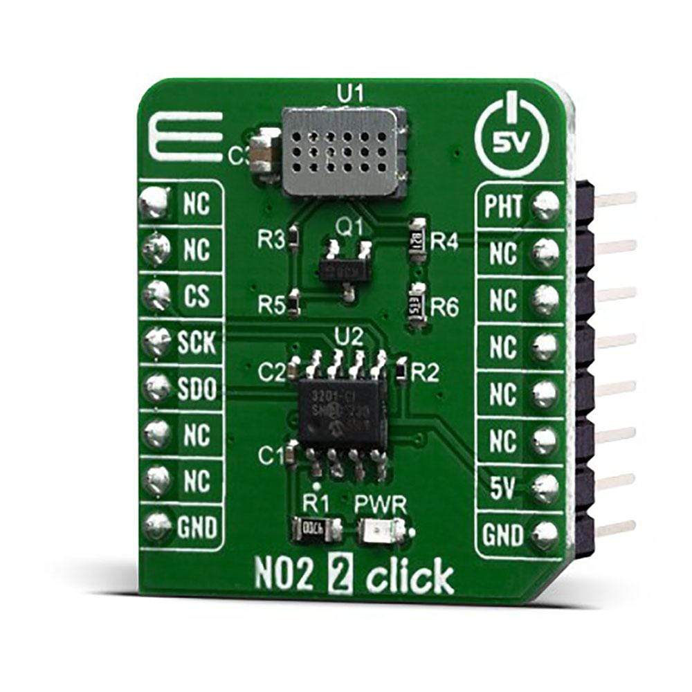
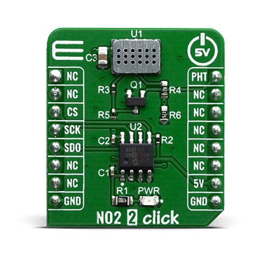
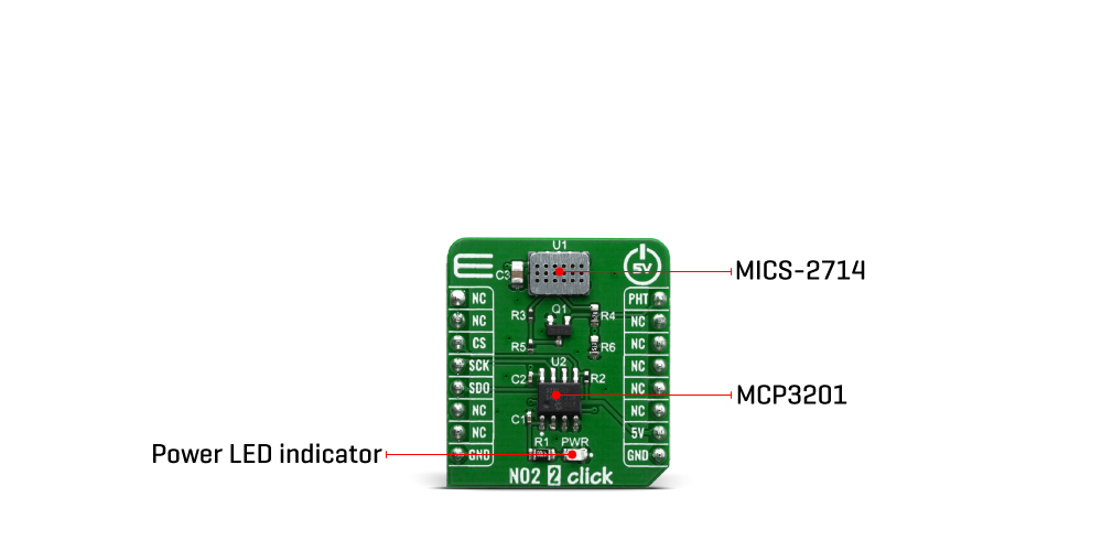
The NO2 2 Click Board™ is a gas sensor Click Board™, equipped with the MiCS-2714, a compact metal oxide (MOS) sensor. This sensor reacts to the presence of nitrogen dioxide (NO2) and hydrogen (H2). Its impedance changes as a result of a catalytic reaction, allowing it to be used in a voltage divider configuration. This voltage can be sampled by an accurate A/D converter (ADC), allowing data to be read directly over the I2C interface. The MiCS-2714 sensor itself is a robust sensor, which can be used in a harsh environment for gas leakage detection, in breath checking applications, early fire detection, etc.
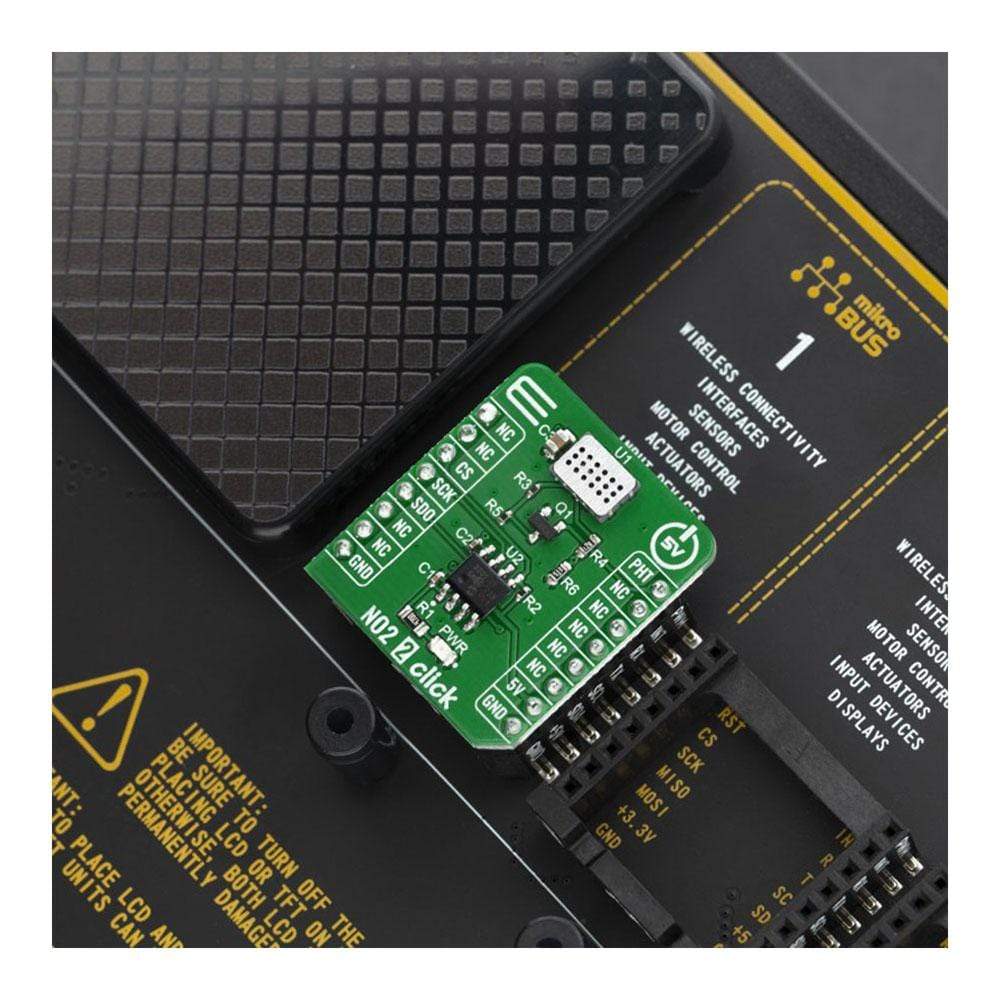
The NO2 2 Click Board™ is supported by a mikroSDK compliant library, which includes functions that simplify software development. This Click Board™ comes as a fully tested product, ready to be used on a system equipped with the mikroBUS™ socket.
Downloads
The NO2 2 Click Board™ contains the required resistances used to form a voltage divider with the sensor, as well as the accurate SAR type ADC with 12-bit resolution which allows the voltage to be converted, using 5V from the mikroBUS rail as a voltage reference. Featuring the MiCS-2714, a robust and reliable gas sensor which requires a minimal number of additional components, the MCP3201, an accurate 12-bit ADC by Microchip, proven in many Click Board™ designs so far, the NO2 2 Click Board™ represents an ideal solution for a rapid development in all kinds of harsh environments of applications such as gas leakage applications, fire detection applications, CO detectors, and similar reducing gasses detecting applications.
How Does The NO2 2 Click Board™ Work?
The NO2 2 Click Board™ is equipped with the MiCS-2714 sensor, a compact MOS sensor from SGX Sensortech. This sensor consists of a micromachined metal oxide semiconductor diaphragm, with an integrated heating resistor. The resistor produces heat which catalyzes the reaction, which in turn affects the electrical resistance of the oxide layer itself. The temperature of the heater is quite high: it is in the range from 350 °C to 550 °C. After the initial preheating period, the sensor can detect gas changes in time intervals below two seconds.
The resistance of the MiCS-2714 sensor does not change linearly with the gas concentration, so a proper calibration must be performed prior to using it for absolute gas concentration measurement applications. The impedance changes the most when used with low gas concentrations. As the atmosphere gets saturated with gas, the impedance changes slower.
The MiCS-2714 sensor is a simple device: it has only four connections. Two pins are the connections of the internal heating element, while the other two pins are the MOS sensor connections. The application is reduced to calculating a proper resistor for the voltage divider. The middle tap between the sensor (as a resistor) and the fixed resistance is used to provide an output voltage. It directly depends on the resistance of the sensor, allowing it to be used as the input into the MCP3201, a low-power 12-bit A/D converter with I2C interface, from Microchip. This ADC allows the output voltage to be translated into a digital information, which can be accessed over the I2C pins on the mikroBUS socket. By using the power supply voltage as the voltage reference for the conversion, this ADC further reduces the complexity of the design, still offering a good conversion quality, thanks to its low noise input. Due to the sensor's inert nature, this ADC is more than fast enough, although it can provide up to 22.3 ksps when operated in the I2C Fast mode.
The NO2 2 Click Board™ is designed to be operated only with 5V logic level. A proper logic voltage level conversion should be performed before the Click Board™ is used with MCUs with logic levels of 3.3V.
SPECIFICATIONS
| Type | Gas,NO2 |
| Applications | It can be used for various applications, such as gas leakage applications, fire detection applications, CO detectors, and similar reducing gasses detecting applications. |
| On-board modules | MiCS-2714 - a compact metal oxide (MOS) sensor from SGX Sensortech |
| Key Features | Robust and reliable MOS sensor, a high-quality 12-bit ADC from Microchip onboard, can detect a range of different redux gasses, ideal for a various application development, etc |
| Interface | SPI |
| Compatibility | mikroBUS |
| Click Board™ size | S (28.6 x 25.4 mm) |
| Input Voltage | 5V |
PINOUT DIAGRAM
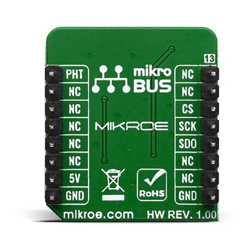
This table shows how the pinout of the NO2 2 Click Board™ corresponds to the pinout on the mikroBUS socket (the latter shown in the two middle columns).
| Notes | Pin |  |
Pin | Notes | |||
|---|---|---|---|---|---|---|---|
| NC | 1 | AN | PWM | 16 | PHT | Preheating | |
| NC | 2 | RST | INT | 15 | NC | ||
| Chip Select | CS | 3 | CS | RX | 14 | NC | |
| SPI Clock | SCK | 4 | SCK | TX | 13 | NC | |
| SPI Data Out | SDO | 5 | MISO | SCL | 12 | NC | |
| NC | 6 | MOSI | SDA | 11 | NC | ||
| NC | 7 | 3.3V | 5V | 10 | 5V | Power Supply | |
| Ground | GND | 8 | GND | GND | 9 | GND | Ground |
ONBOARD SETTINGS AND INDICATORS
| Label | Name | Default | Description |
|---|---|---|---|
| LD1 | PWR | - | Power LED Indicator |
NO2 2 Click Board™ ELECTRICAL SPECIFICATIONS
| Description | Min | Typ | Max | Unit |
|---|---|---|---|---|
| Measurement range | 0 | - | 10 | ppm |
| Response time | - | 200 | - | s |
| Operating Temperature Range (recommended) | -30 | - | 85 | ˚C |
| Operating Humidity Range (non-condensing) | 5 | - | 95 | % RH |
| General Information | |
|---|---|
Part Number (SKU) |
MIKROE-3700
|
Manufacturer |
|
| Physical and Mechanical | |
Weight |
0.02 kg
|
| Other | |
Country of Origin |
|
HS Code Customs Tariff code
|
|
EAN |
8606018719983
|
Warranty |
|
Frequently Asked Questions
Have a Question?
Be the first to ask a question about this.

