


Mikroelektronika d.o.o.
SKU: MIKROE-5691Magnetic Rotary 5 Click Board
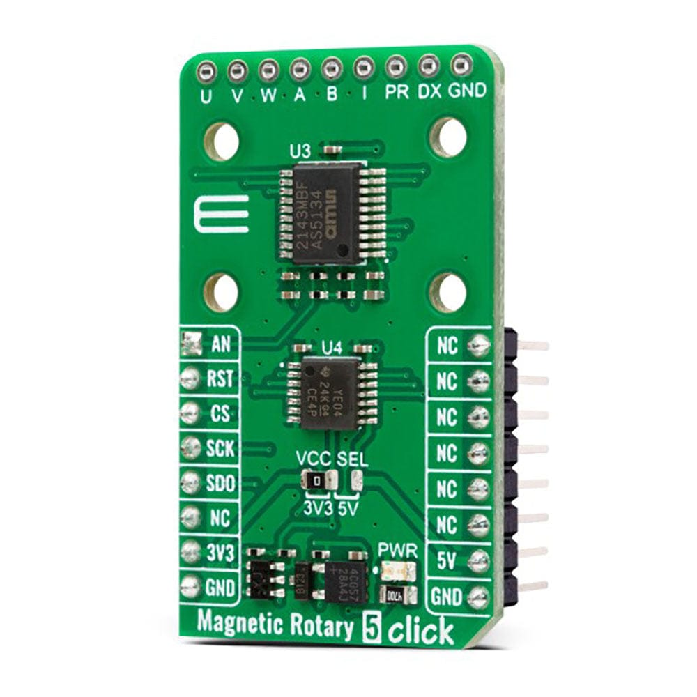
Magnetic Rotary 5 Click Board
Couldn't load pickup availability
Key Features
- Accurate angular measurement over a full turn of 360º, user programmable zero position and sensitivity, high speeds, data transmission via 3-wire or analog signal, incremental and commutation signal, low power consumption, daisy chain mode, and more
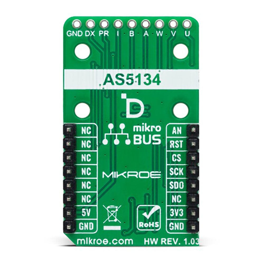
- Based on the AS5134 - contactless magnetic rotary encoder from ams AG
- Can be used for contactless rotary position sensing, rotary switches (human-machine interface), AC/DC motor position control, and brushless DC motor position control
- mikroBUS: SPI and Analogue Interfaces
Experience the Future of Magnet-Position Sensing with Magnetic Rotary 5 Click Board™
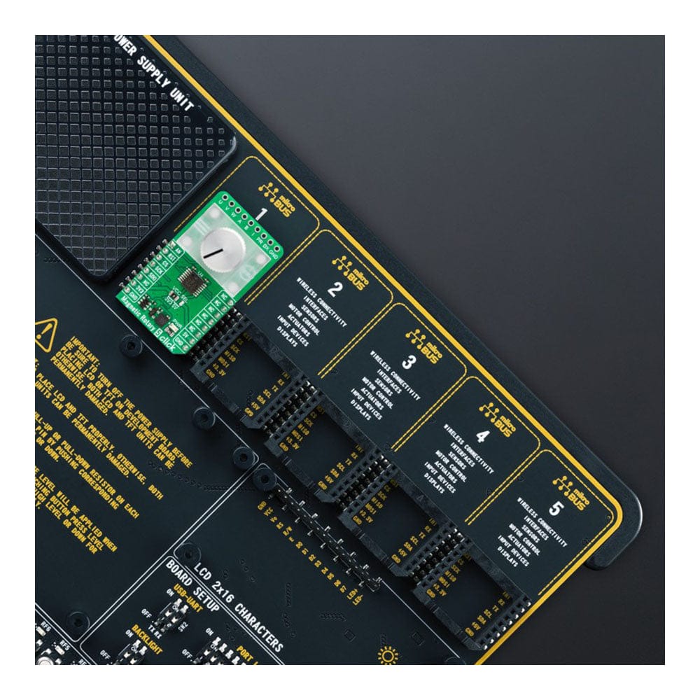
Introducing the Magnetic Rotary 5 Click Board™, a cutting-edge add-on board engineered for precise magnet-position sensing. Experience exceptional accuracy with the AS5134, a contactless magnetic rotary encoder from ams AG designed for full 360º angular measurement. Simplify your angle measurements with a basic two-pole magnet rotating over the chip's centre, integrating a Hall element, analogue front end, and digital signal processing.
High Resolution and Speed for Unmatched Performance
Boasting an impressive 8.5-bit resolution, the Magnetic Rotary 5 Click Board™ offers 360 positions per revolution. Achieve high-speed performance with a maximum RPM of 76,875, accommodating a wide range of magnetic fields from 20 to 80mT. The onboard header supports incremental, and commutation signals for A/B/I and U/V/W while also featuring pins for Daisy Chain Mode and OTP programming.
Versatility for a Multitude of Applications
Perfect for contactless rotary position sensing, rotary switches (human-machine interface), AC/DC motor position control, and brushless DC motor position control, the Magnetic Rotary 5 Click Board™ delivers exceptional versatility for your projects.
Seamless Integration with mikroSDK Compliant Library
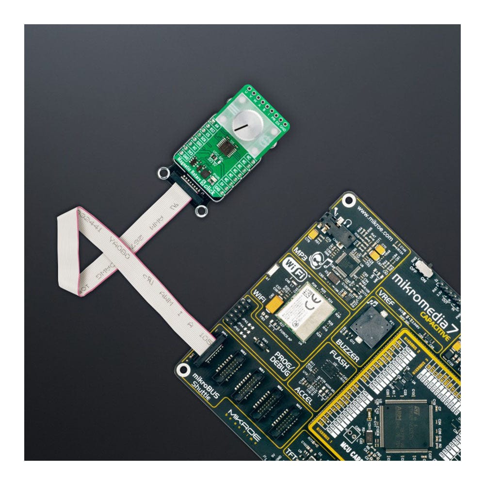
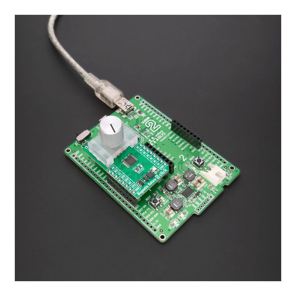
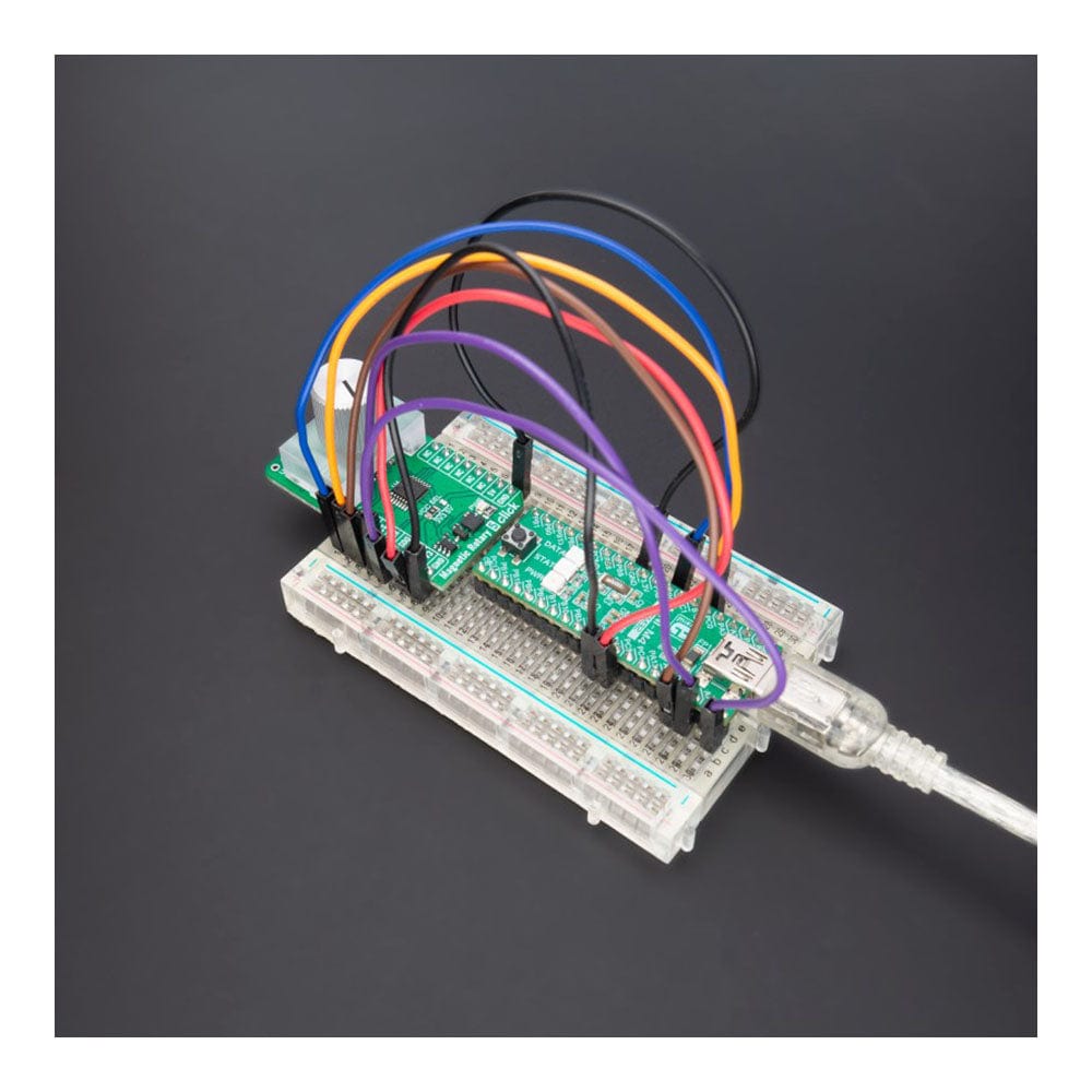
Effortlessly streamline your software development with a mikroSDK-compliant library featuring functions that support the Magnetic Rotary 5 Click Board™. Arriving as a fully-tested product, this Click board™ is ready for use on any system equipped with a mikroBUS™ socket.
How Does The Magnetic Rotary 5 Click Board™ Work?
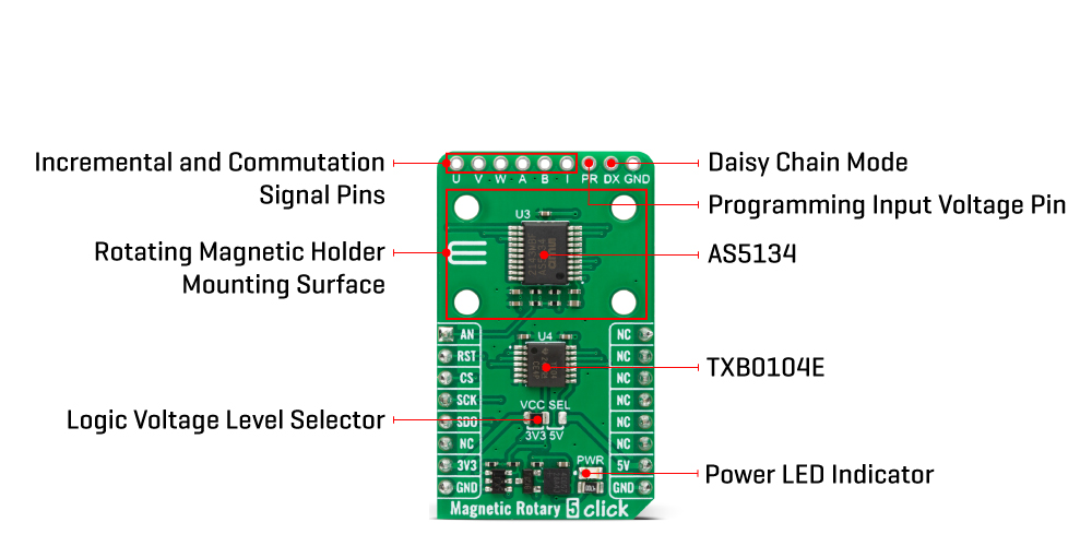
The Magnetic Rotary 5 Click Board™ is based on the AS5134, a contactless magnetic rotary encoder from ams AG for accurate angular measurement over a full turn of 360º. The AS5134 is an innovative system-on-chip that offers a wide range of features and capabilities. In addition to its integrated Hall elements, analogue front end, and digital signal processing, this chip is designed with power efficiency in mind. It features a Power Down Mode and fast Start-Up sequence and measurement cycles, allowing for low average power consumption. To measure the angle, only a simple two-pole magnet rotating over the centre of the chip is required. The absolute angle measurement instantly indicates the magnet's angular position with a resolution of 8.5bit equals 360 positions per revolution. It allows high speeds up to 76875RPM and a wide magnetic field input range from 20 to 80mT.
Thanks to its high precision and ability to measure the absolute angle, the AS5134 is suitable for various applications, including contactless position sensing and rotary switches, which can provide a human-machine interface. This chip is also well-suited for motor position control, including AC/DC and Brushless motor position control. This Click board™ communicates with the host MCU using a serial SPI 3-wire read-only connection, only to provide the angular data. An additional way of processing angular data is through the analog pin of the mikroBUS™ socket. With the addition of a lowpass filter at the PWM output pin of the AS5134, this configuration produces an analog voltage proportional to the angle. If the AS5134 angular data is invalid, the PWM output will remain low; thus, the analog output will be 0V.
The Magnetic Rotary 5 Click Board™ also comes with an unpopulated header reserved for incremental and commutation signals of their respective A/B/I and U/V/W signals. The phase shift between channels A and B indicates the direction of the magnet movement. Channel A leads channel B at a clockwise magnet rotation by 90 electrical degrees, while channel B leads channel A at a counter-clockwise rotation. Brushless DC (BLDC) motors are also controllable through a standard UVW commutation interface with a programmable number of pole pairs from 1 to 6. These signals will control the electrical angle information according to the number of pole pairs and the actual mechanical angle position.
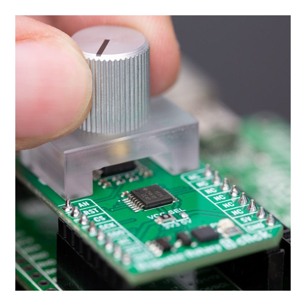
In addition, this unpopulated header also contains two additional pins marked PR and DX. The PR pin serves to supply the necessary DC voltage in the range of 8 to 8.5V to activate the possibility of permanent programming. Users have the option of zero position programming and magnetic field optimization. Meanwhile, the DX pin can implement a daisy chain mode, providing even greater flexibility in system design. With these added features, the board can be configured for either a two-wire or three-wire mode, depending on the application's specific requirements. Also, unique addition to this board is a position for a rotary magnet holder designed to be used alongside a magnetic rotary position sensor allowing fast prototyping and quick measurements during development.
Although the AS5134 uses 5V as the primary power source, this Click board™ can operate with either 3.3V or 5V logic voltage levels selected via the VCC SEL jumper thanks to the voltage level translator, the TXB0104E. This way, both 3.3V and 5V capable MCUs can use the communication lines properly. However, the Click board™ comes equipped with a library containing easy-to-use functions and an example code that can be used, as a reference, for further development.
SPECIFICATIONS
| Type | Magnetic |
| Applications | It can be used for contactless rotary position sensing, rotary switches (human-machine interface), AC/DC motor position control, and brushless DC motor position control. |
| On-board modules | AS5134 - contactless magnetic rotary encoder from ams |
| Key Features | Accurate angular measurement over a full turn of 360º, user programmable zero position and sensitivity, high speeds, data transmission via 3-wire or analogue signal, incremental and commutation signal, low power consumption, daisy chain mode, and more |
| Interface | Analog,SPI |
| Compatibility | mikroBUS |
| Click board size | M (42.9 x 25.4 mm) |
| Input Voltage | 3.3V or 5V |
PINOUT DIAGRAM
This table shows how the Magnetic Rotary 5 Click Board™ pinout corresponds to the pinout on the mikroBUS™ socket (the latter shown in the two middle columns).
| Notes | Pin | Pin | Notes | ||||
|---|---|---|---|---|---|---|---|
| Analog Signal | AN | 1 | AN | PWM | 16 | NC | |
| NC | 2 | RST | INT | 15 | NC | ||
| SPI Chip Select | CS | 3 | CS | RX | 14 | NC | |
| SPI Clock | SCK | 4 | SCK | TX | 13 | NC | |
| SPI Data OUT | SDO | 5 | MISO | SCL | 12 | NC | |
| NC | 6 | MOSI | SDA | 11 | NC | ||
| Power Supply | 3.3V | 7 | 3.3V | 5V | 10 | 5V | Power Supply |
| Ground | GND | 8 | GND | GND | 9 | GND | Ground |
ONBOARD SETTINGS AND INDICATORS
| Label | Name | Default | Description |
|---|---|---|---|
| LD1 | PWR | - | Power LED Indicator |
| JP1 | PWR | Left | Logic Level Voltage Selection 3V3/5V: Left position 3V3, Right position 5V |
| J1 | - | Unpopulated | Incremental and Commutation Signals Header |
| J2 | - | Unpopulated | Programming Voltage and Daisy Chain Mode Header |
MAGNETIC ROTARY 5 CLICK ELECTRICAL SPECIFICATIONS
| Description | Min | Typ | Max | Unit |
|---|---|---|---|---|
| Supply Voltage | 3.3 | - | 5 | V |
| Rotation Angle Range | 0 | - | 360 | °C |
| Magnetic Field Range | 20 | - | 80 | mT |
| Magnetic Rotation Speed | - | - | 76875 | RPM |
| Resolution | - | 8.5 | - | bit |
Software Support
We provide a library for the Magnetic Rotary 5 Click Board™ as well as a demo application (example), developed using MIKROE compilers. The demo can run on all the main MIKROE development boards.
The package can be downloaded/installed directly from NECTO Studio The package Manager (recommended), downloaded from our LibStock™ or found on the MIKROE Github account.
Library Description
This library contains API for Magnetic Rotary 5 Click driver.
Key functions
-
magneticrotary5_read_angleThis function reads the magnetic angle and automatic gain control (AGC) values measured by the sensor. -
magneticrotary5_read_mt_cntThis function reads the multi-turn counter value. With each zero transition in any direction, the output of a special counter is incremented or decremented. -
magneticrotary5_read_voltageThis function reads the raw ADC value and converts it to a proportional voltage level.
Example Description
This example demonstrates using Magnetic Rotary 5 Click board™ by reading and displaying the magnet angular position and the AGC and multi-turn counter values.
void application_task ( void )
 {
     uint8_t agc = 0;
     uint16_t angle = 0;
     int16_t mt_cnt = 0;
     float voltage = 0;
     if ( MAGNETICROTARY5_OK == magneticrotary5_read_angle ( &magneticrotary5, &agc, &angle ) )
     {
         log_printf ( &logger, "rn AGC: %urn Angle: %urn", ( uint16_t ) agc, angle );
     }
     if ( MAGNETICROTARY5_OK == magneticrotary5_read_mt_cnt ( &magneticrotary5, &mt_cnt ) )
     {
         log_printf ( &logger, " Multi turn counter: %drn", mt_cnt );
     }
     if ( MAGNETICROTARY5_OK == magneticrotary5_read_voltage ( &magneticrotary5, &voltage ) )
     {
         log_printf( &logger, " AN Voltage : %.3f Vrn", voltage );
     }
     Delay_ms ( 100 );
 }
The full application code, and ready to use projects can be installed directly from NECTO Studio The package Manager (recommended), downloaded from our LibStock™ or found on MIKROE Github account.
Other MIKROE Libraries used in the example:
- MikroSDK.Board
- MikroSDK.Log
- Click.MagneticRotary5
Additional Notes and Information
Depending on the development board you are using, you may need USB UART Click Board™, USB UART 2 Click or RS232 Click to connect to your PC, for development systems with no UART to USB interface available on the board. UART terminal is available in all MIKROE compilers.
MIKROSDK
The Magnetic Rotary 5 Click Board™ is supported with mikroSDK - MikroE Software Development Kit, which needs to be downloaded from the LibStock and installed for the compiler you are using to ensure proper operation of mikroSDK compliant Click board™ demo applications.
Magnetic Rotary 5 Click Board
Frequently Asked Questions
Ask a Question-
Can the Magnetic Rotary 5 Click Board™ be used in industrial applications?
Yes, the Magnetic Rotary 5 Click Board™ can be used in various industrial applications that require precise angular measurement and magnet-position sensing. Its compact design makes it suitable for space-constrained environments.
-
Does the Magnetic Rotary 5 Click Board™ require any additional components or software?
The Magnetic Rotary 5 Click Board™ comes with all the necessary components onboard. You may need to connect it to your development board and utilize the appropriate software libraries to access and interpret the sensor data.
-
Is the Magnetic Rotary 5 Click Board™ compatible with other development boards?
Yes, the Magnetic Rotary 5 Click Board™ is designed to be compatible with a wide range of development boards that support the MikroBUS™ socket standard. You can easily integrate it into your existing projects.
-
How can the Magnetic Rotary 5 Click Board™ enhance my projects?
By integrating the Magnetic Rotary 5 Click Board™ into your projects, you can achieve precise magnet-position sensing, enabling you to accurately measure angular movements. This can be particularly useful in robotics, automation, or any application requiring precise rotational measurements.
-
Why should I choose the Magnetic Rotary 5 Click Board™?
The Magnetic Rotary 5 Click Board™ offers precise magnet-position sensing and accurate angular measurement in a compact design, making it a valuable addition to your projects.
-
Where can I purchase the Magnetic Rotary 5 Click Board™?
You can purchase the Magnetic Rotary 5 Click Board™ at The Debug Store.
-
Where can I purchase the Magnetic Rotary 5 Click Board™?
You can purchase the Magnetic Rotary 5 Click Board™ at The Debug Store.
-
What is the Magnetic Rotary 5 Click Board™?
The Magnetic Rotary 5 Click Board™ is a compact device that enables precise magnet-position sensing and accurate angular measurement for your projects.