


Mikroelektronika d.o.o.
SKU: MIKROE-5644Brushless 25 Click Board
Brushless 25 Click Board
Couldn't load pickup availability
Key Features
- Sensorless motor control algorithm, high output current, low power sleep mode, overcurrent detection and protection, fault diagnostic output, thermal warning and shutdown, PWM and analog motor control, brake function, direction spinning function, and more
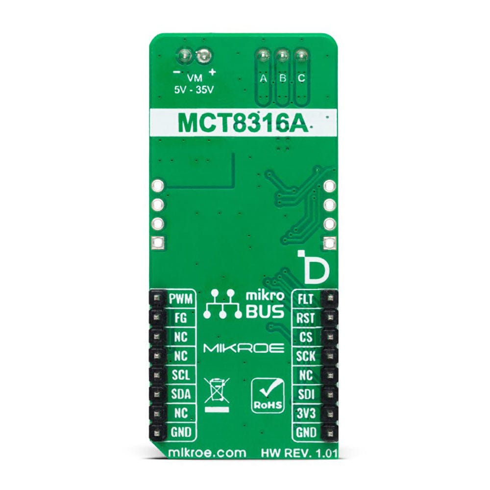
- Based on the MCT8316A - high-speed sensorless trapezoidal control integrated FET BLDC driver from Texas Instruments
- Can be used for driving three-phase brushless DC motors, solenoids or other loads up to 8A output current rating
- mikroBUS: I2C and SPI Interfaces
The Brushless 25 Click Board™: Unleash the Power of Brushless DC Motors!
Introducing the Brushless 25 Click Board™, the compact add-on board that revolutionizes how you control brushless DC motors with any MCU. With its advanced features and high-performance components, this Click board™ opens up a world of possibilities for your motor-driven projects.
Powerful Performance, Precise Control
The Brushless 25 Click Board™ is equipped with the state-of-the-art MCT8316A, a high-speed sensorless trapezoidal control integrated FET BLDC driver from Texas Instruments. This cutting-edge driver provides three individually controllable drivers, giving you unparalleled control over your three-phase BLDC motor, solenoids, or other loads.
Each output driver channel of the Brushless 25 Click Board™ features N-channel power MOSFETs configured in a 1/2-H-bridge configuration. With a total of six MOSFETs, this board ensures optimal performance and efficiency for your motor-driven applications.
Reliable and Protected
Worried about voltage fluctuations or electrical faults damaging your system? Don't be. The Brushless 25 Click Board™ offers a wide operating voltage range from 4.5V to 35V, accommodating various power supply setups. Additionally, it comes equipped with several built-in protection circuits, including undervoltage, overvoltage, charge pump faults, overcurrent, and overtemperature protection. Rest assured that your motor and the Click board™ itself are always safe and secure.
Seamless Integration and Easy Development
The Brushless 25 Click Board™ is designed to make your development process smooth and hassle-free. It is supported by a mikroSDK-compliant library, providing you with a collection of functions that simplify software development. Say goodbye to complex coding and hello to streamlined development!
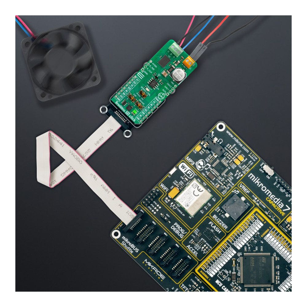
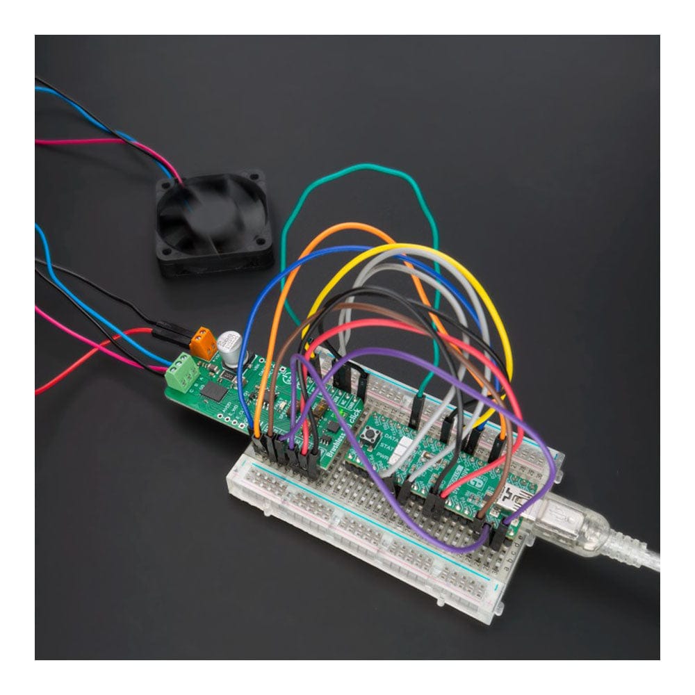
Not only is the Brushless 25 Click Board™ a powerful tool, but it also comes as a fully tested product, ready to be integrated into your system. Simply plug it into a system equipped with the mikroBUS™ socket, and you're ready to unleash the full potential of your motor-driven projects.
Upgrade your motor control capabilities with the Brushless 25 Click Board™ today and experience a new level of precision and performance. Don't miss out on this game-changing solution for driving three-phase brushless DC motors up to 8A peak output current rating. Order yours now!


How Does The Brushless 25 Click Board™ Work?
The Brushless 25 Click Board™ is based on the MCT8316A, a high-speed sensorless trapezoidal control integrated FET BLDC driver from Texas Instruments. It is the ideal solution for applications requiring the high-speed operation of up to 3kHz of electrical speed, a very fast startup time of under 50ms for 12V to 24V BLDC motors, and fast deceleration of under 150ms. The driver's control is highly configurable through register settings stored in an onboard non-volatile EEPROM. This feature allows the device to operate as a stand-alone device once it has been configurated. In addition, the MCT8316A allows a high level of monitoring, where any variable in the algorithm can be observed as an analog output via two 12-bit DACs.
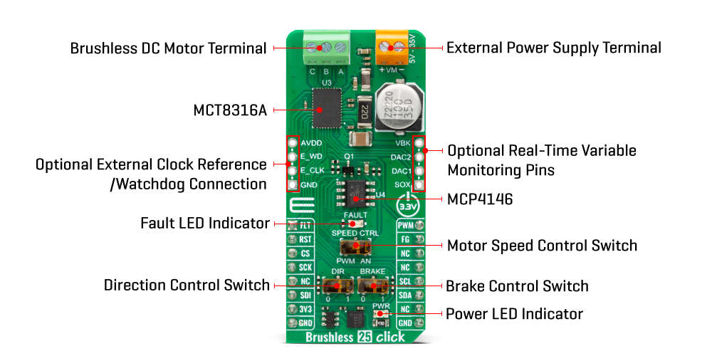
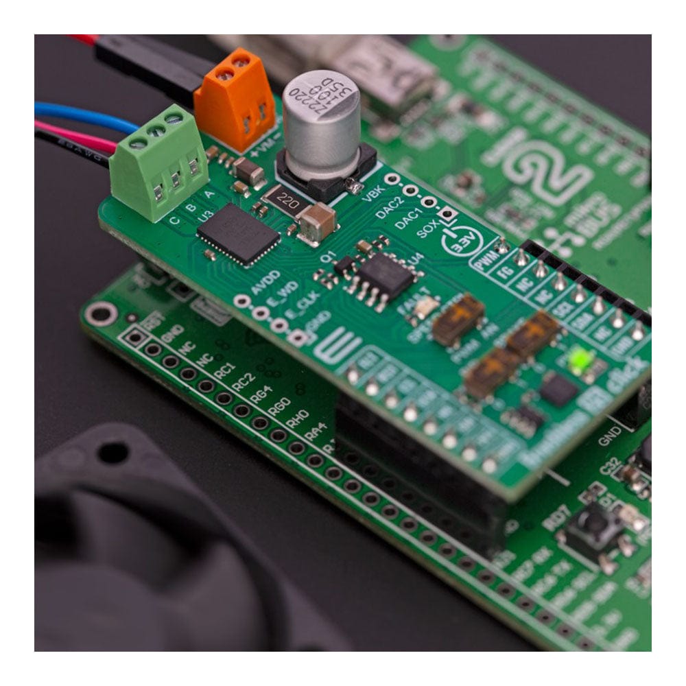
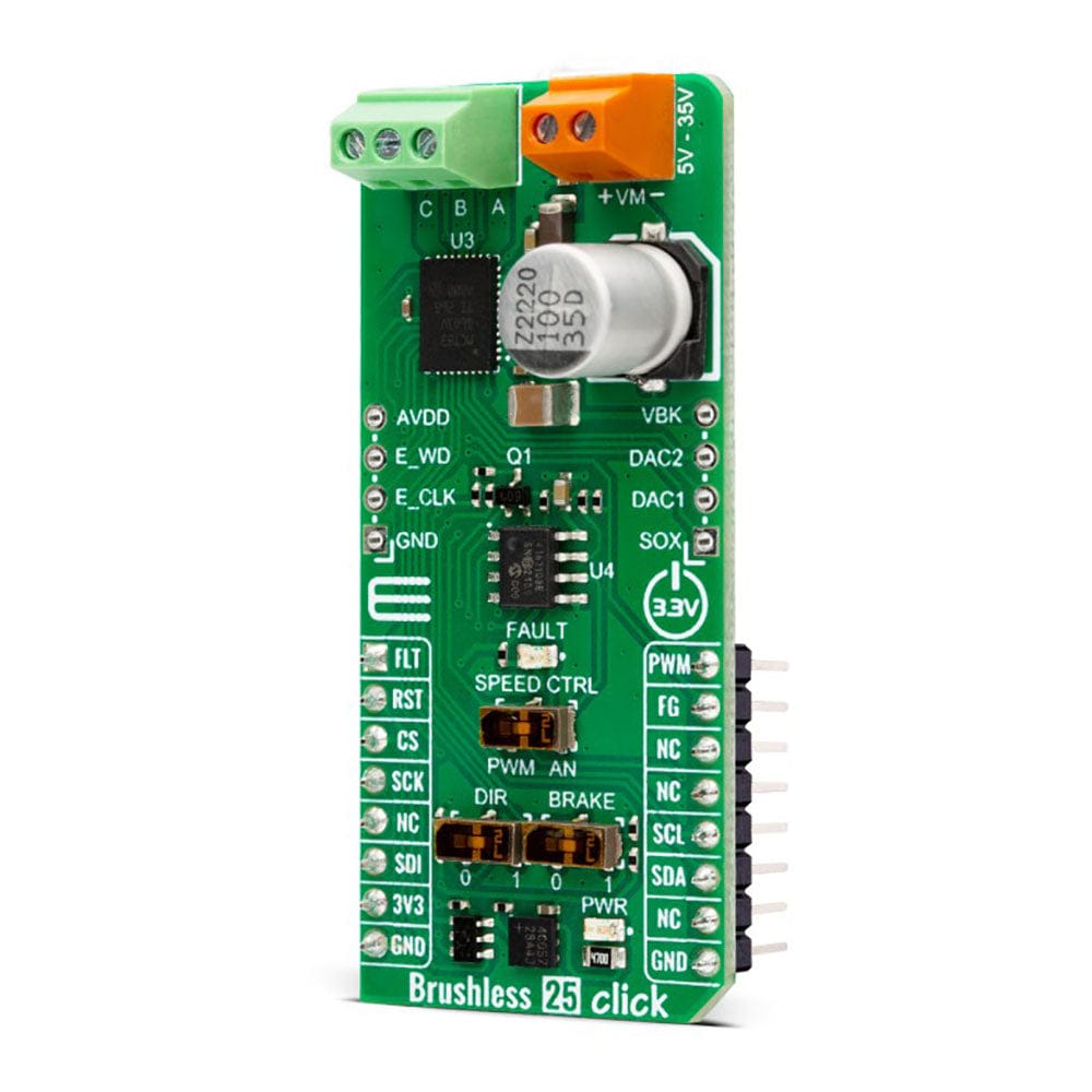
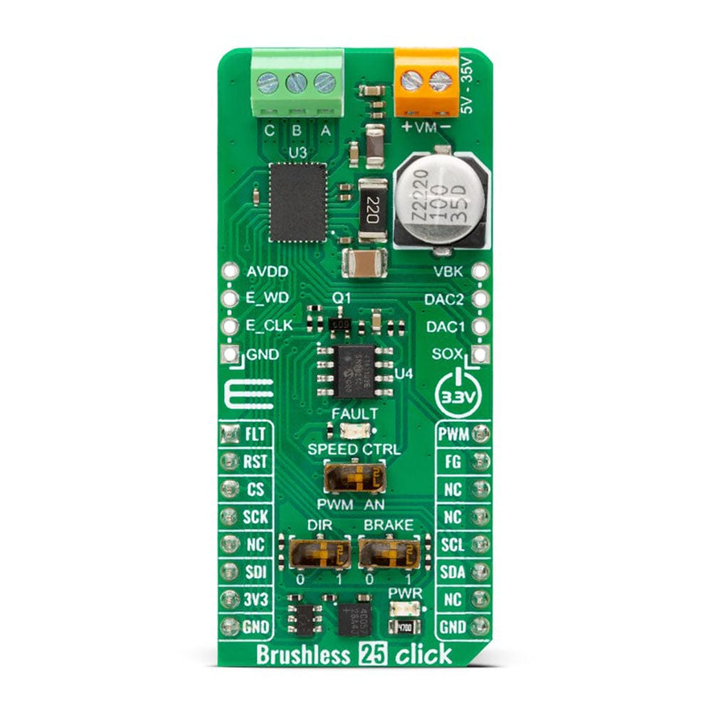
The Brushless 25 Click Board™ uses a standard I2C 2-Wire interface that allows the host MCU to configure EEPROM settings and read detailed fault and motor state information. If a fault condition occurs, the MCT8316A will pull the FLT pin to a low logic state, with a FAULT LED as a visual presentation. The FG pin is used as a motor speed indicator and provides pulses proportional to motor speed. For connecting the three-phase BLDC motor, this Click board™ features the half-bridge output CBA screw terminal and a VM terminal for an external motor power supply. The RST pin can set the motor driver to sleep mode by turning all MOSFETs OFF.
There are three switches to control the connected motor manually. The speed can be controlled by a PWM or analog value, which can be selected via the SPEED CTRL switch. The PWM signal can be set over the corresponding pin of the mikroBUS™ socket, while the analog value can be set over the MCP4161, an 8-bit, single SPI digital potentiometer with non-volatile memory from Microchip. The motor driver expects up to 95KHz of PWM frequency or an analog voltage in 732μV resolution. In addition, this is also a way to wake up the motor driver from sleep mode.
The DIR switch changes the direction of the motor spinning with 0 and 1 positions. The low position (0) sets the phase driving sequence as ABC, while the high position (1) sets the ACB sequence. The I2C interface can overwrite this input. The Brake switch also has two states, with high entering the brake state. The MCT8316A will decrease the output speed to the threshold value and stay in the brake state as long as this switch is in a high position. This input also can be overwritten by the I2C interface.
In addition, the Brushless 25 Click Board™ comes with two headers above the mikroBUS™ socket for some optional feature addition. The VBK pin on the right-side unpopulated header is an output voltage pin from the internal buck regulator for some external loads. Other pins on this header are for monitoring algorithm variables and phase current feedback through DAC and SOX pins (the SOX pin can also be configured as one of the DAC pins). On the left side is an unpopulated header with E_WD and E_CLK signals acting as the external clock reference and watchdog input pins.
Thie Brushless 25 Click Board™ can only be operated with a 3.3V logic voltage level. The board must perform appropriate logic voltage level conversion before using MCUs with different logic levels. However, the Click board™ comes equipped with a library containing functions and an example code that can be used as a reference for further development.
SPECIFICATIONS
| Type | Brushless |
| Applications | Can be used for driving three-phase brushless DC motors, solenoids or other loads up to 8A output current rating |
| On-board modules | MCT8316A - high-speed sensorless trapezoidal control integrated FET BLDC driver from Texas Instruments |
| Key Features | Sensorless motor control algorithm, high output current, low power sleep mode, overcurrent detection and protection, fault diagnostic output, thermal warning and shutdown, PWM and analog motor control, brake function, direction spinning function, and more |
| Interface | I2C,SPI |
| Compatibility | mikroBUS |
| Click board size | L (57.15 x 25.4 mm) |
| Input Voltage | 3.3V,External |
PINOUT DIAGRAM
This table shows how the pinout on f the Brushless 25 Click Board™ corresponds to the pinout on the mikroBUS™ socket (the latter shown in the two middle columns).
| Notes | Pin | Pin | Notes | ||||
|---|---|---|---|---|---|---|---|
| Fault Indicator | FLT | 1 | AN | PWM | 16 | PWM | PWM Signal |
| Reset | RST | 2 | RST | INT | 15 | FG | Motor Speed Indicator |
| SPI Chip Select | CS | 3 | CS | RX | 14 | NC | |
| SPI Clock | SCK | 4 | SCK | TX | 13 | NC | |
| NC | 5 | MISO | SCL | 12 | SCL | I2C Clock | |
| SPI Data IN | SDI | 6 | MOSI | SDA | 11 | SDA | I2C Data |
| Power Supply | 3.3V | 7 | 3.3V | 5V | 10 | NC | |
| Ground | GND | 8 | GND | GND | 9 | GND | Ground |
ONBOARD SETTINGS AND INDICATORS
| Label | Name | Default | Description |
|---|---|---|---|
| LD1 | PWR | - | Power LED Indicator |
| LD2 | Fault | - | Fault LED Indicator |
| SW1 | SPEED CTRL | Right | Speed Control Selection PWM/AN: Left position PWM, Right position AN |
| SW2 | BRAKE | Right | Brake Selection 0/1: Left position 0, Right position 1 |
| SW3 | DIR | Right | Direction Spinning Selection 0/1: Left position 0, Right position 1 |
BRUSHLESS 25 CLICK ELECTRICAL SPECIFICATIONS
| Description | Min | Typ | Max | Unit |
|---|---|---|---|---|
| Supply Voltage | - | 3.3 | - | V |
| External Supply Voltage Input | 4.5 | - | 35 | V |
| Maximum Output Current | - | - | 8 | A |
Software Support
We provide a library for the Brushless 25 Click Board™ as well as a demo application (example), developed using MIKROE compilers. The demo can run on all the main MIKROE development boards.
The package can be downloaded/installed directly from NECTO Studio The package Manager (recommended), downloaded from our LibStock™ or found on MIKROE Github account.
Library Description
This library contains API for Bthe Brushless 25 Click Board™ driver.
Key functions
-
brushless25_register_writeBrushless 25 data writing function. -
brushless25_register_readBrushless 25 data reading function. -
brushless25_set_speed_valueBrushless 25 set speed function.
Example Description
Application example shows the device's capability of controlling the brushless motor speed and state of the driver.
void application_task ( void )
 {
     uint32_t tmp_data = 0;
     uint16_t spd_data = 0;
     uint16_t voltage_data = 0;


     brushless25_register_read( &brushless25, BRUSHLESS25_SYS_STATUS2_REG, &tmp_data );
     tmp_data &= BRUSHLESS25_STATE_MASK;

     switch ( tmp_data )
     {
         case BRUSHLESS25_STATE_SYSTEM_IDLE:
         {
             log_info( &logger, " System is idle " );
             break;
         }
         case BRUSHLESS25_STATE_MOTOR_START:
         {
             log_info( &logger, " Motor is starting " );
             break;
         }
         case BRUSHLESS25_STATE_MOTOR_RUN:
         {
             log_info( &logger, " Motor is running" );
             if ( ( speed_val < 10 ) && ( sw_data == 0 ) )
             {
                 speed_val++;
                 if ( speed_val == 10 )
                 {
                     sw_data = 1;
                 }
             }
             else if ( ( speed_val > 3 ) && ( sw_data == 1 ) )
             {
                 speed_val--;
                 if ( speed_val == 3 )
                 {
                     sw_data = 0;
                 }
             }

             break;
         }
         case BRUSHLESS25_STATE_MOTOR_ALIGN:
         {
             log_info( &logger, " Motor is aligning " );
             break;
         }
         case BRUSHLESS25_STATE_MOTOR_IDLE:
         {
             log_info( &logger, " Motor is in idle mode " );
             break;
         }
         case BRUSHLESS25_STATE_MOTOR_STOP:
         {
             log_info( &logger, " Motor is stoped " );
             brushless25_set_brake_state( &brushless25, BRUSHLESS25_BRAKE_ON );
             break;
         }
         case BRUSHLESS25_STATE_FAULT:
         {
             log_error( &logger, " Fault accured " );
             brushless25_set_brake_state( &brushless25, BRUSHLESS25_BRAKE_ON );
             for ( ; ; );
         }
         case BRUSHLESS25_STATE_MOTOR_BRAKE:
         {
             log_info( &logger, " Motor brake is on " );
             brushless25_set_brake_state( &brushless25, BRUSHLESS25_BRAKE_OFF );
             break;
         }
         default:
         {
             break;
         }
     }

     brushless25_set_speed_value( &brushless25, ( speed_val * 10 ) );
     Delay_ms ( 1000 );
     brushless25_register_read( &brushless25, BRUSHLESS25_SYS_STATUS2_REG, &tmp_data );
     spd_data = ( uint16_t ) tmp_data / 10;
     brushless25_register_read( &brushless25, BRUSHLESS25_SYS_STATUS1_REG, &tmp_data );
     voltage_data = ( ( uint16_t ) ( tmp_data >> 16 ) / 10 );

     log_printf( &logger, " Motor speed: %d Hz rn", spd_data );
     log_printf( &logger, " Motor voltage: %d V rn", voltage_data );
     log_printf( &logger, " --------------------- rn" );
     Delay_ms ( 1000 );
 }
The full application code, and ready to use projects can be installed directly from NECTO Studio The package Manager (recommended), downloaded from our LibStock™ or found on MIKROE Github account.
Other MIKROE Libraries used in the example:
- MikroSDK.Board
- MikroSDK.Log
- Click.Brushless25
Additional Notes and Information
Depending on the development board you are using, you may need USB UART Click Board™, USB UART 2 Click or RS232 Click to connect to your PC, for development systems with no UART to USB interface available on the board. UART terminal is available in all MIKROE compilers.
MIKROSDK
Thie Brushless 25 Click Board™ is supported with mikroSDK - MIKROE Software Development Kit. To ensure proper operation of mikroSDK compliant Click board™ demo applications, mikroSDK should be downloaded from the LibStock and installed for the compiler you are using.
Brushless 25 Click Board
Frequently Asked Questions
Ask a Question-
Is the Brushless 25 Click Board™ a fully tested product?
Yes, the Brushless 25 Click Board™ is a fully tested product, ready to be used on a system equipped with the mikroBUS™ socket.
-
Does the Brushless 25 Click Board™ come with software development support?
Yes, the Brushless 25 Click Board™ is supported by a mikroSDK compliant library, which includes functions that simplify software development.
-
What is the maximum peak output current rating of the Brushless 25 Click Board™?
The Brushless 25 Click Board™ is capable of driving three-phase brushless DC motors with up to 8A peak output current rating.
-
What built-in protection circuits does the Brushless 25 Click Board™ have?
The Brushless 25 Click Board™ includes several built-in protection circuits, such as undervoltage, overvoltage, charge pump faults, overcurrent, and overtemperature.
-
What is the operating voltage range of the Brushless 25 Click Board™?
The Brushless 25 Click Board™ has a wide operating voltage range from 4.5V to 35V.
-
How does the output driver channel of the Brushless 25 Click Board™ work?
Each output driver channel consists of N-channel power MOSFETs, totaling six, configured in a 1/2-H-bridge configuration.
-
What is the main feature of the Brushless 25 Click Board™?
The Brushless 25 Click Board™ features the MCT8316A, a high-speed sensorless trapezoidal control integrated FET BLDC driver from Texas Instruments. It provides three individually controllable drivers designed for driving a three-phase BLDC motor, solenoids, or other loads.
-
What is the Brushless 25 Click Board™?
The Brushless 25 Click Board™ is a compact add-on board that enables control of brushless DC (three-phase BLDC) motors with any MCU.