


Mikroelektronika d.o.o.
SKU: MIKROE-5585Magnetic Rotary 6 Click Board
Magnetic Rotary 6 Click Board
Couldn't load pickup availability
Key Features
- Good resolution for motor and position control, independent output interfaces, self-diagnostics, immune to external stray field, low power consumption, highest reliability and durability, rotary magnet holder, and more
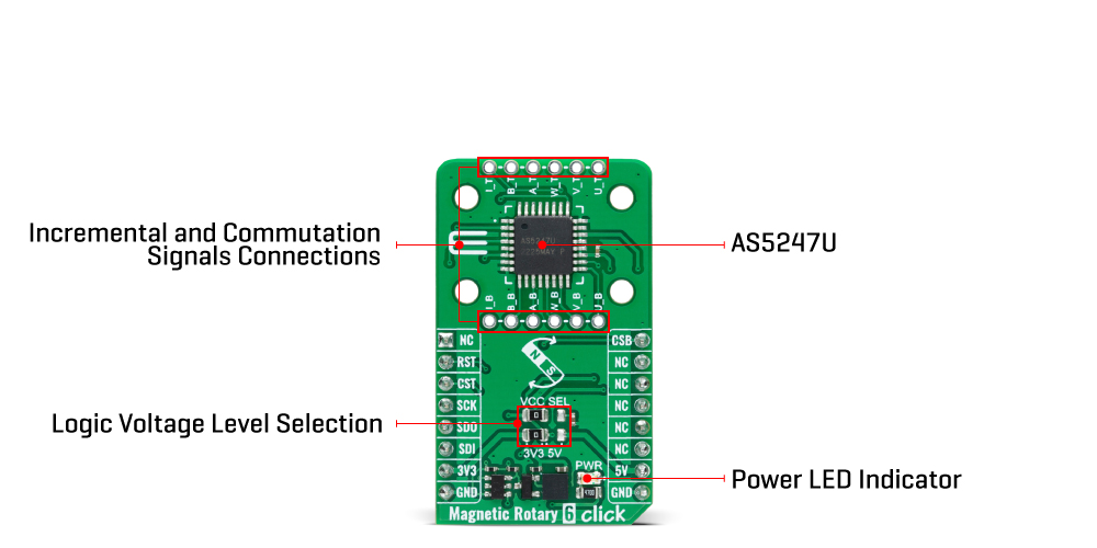
- Based on the AS5247U - rotary position sensor for fast absolute angle measurement over a full 360-degree range from ams AG
- Can be used to support BLDC motor commutation for the most challenging automotive and safety-critical applications
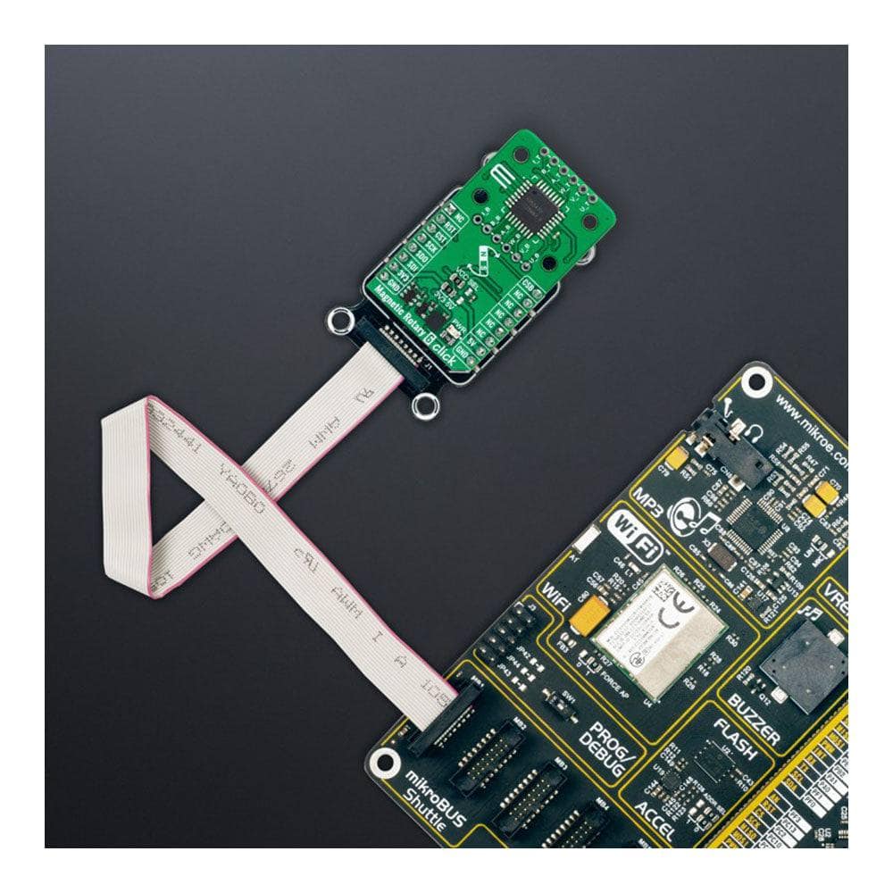
- mikroBUS: SPI Interface
The Magnetic Rotary 6 Click Board™
Upgrade your sensing capabilities with the Magnetic Rotary 6 Click Board™ - a compact and accurate magnet-position sensing add-on board.
Precise Angle Measurement
The AS5247U, a high-resolution dual rotary position sensor from ams AG, offers fast absolute angle measurement over a full 360-degree range. This board provides unparalleled accuracy with almost 0 latency and integrated dynamic angle error compensation (DAEC™).
Robust Design
The AS5047D is designed with a robust casing that suppresses the influence of any homogenous external stray magnetic field, ensuring accurate readings every time. Onboard headers are reserved for incremental and commutation signals of their respective A/B/I and U/V/W signals, with a maximum resolution of 16384 steps/4096 pulses per revolution.
Self-Diagnostics Features
The Magnetic Rotary 6 Click Board™ also includes embedded self-diagnostics features to ensure reliable operation, making it ideal for safety-critical applications such as BLDC motor commutation in the automotive industry.
mikroSDK Compliant Library
The Magnetic Rotary 6 Click Board™ is supported by a mikroSDK-compliant library, which includes functions that simplify software development, so you can start using this powerful add-on board right away.
Ready-to-Use Product
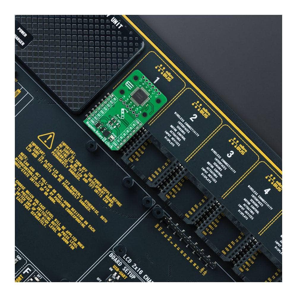
This Click board™ has been fully tested and is ready to be used on a system equipped with the mikroBUS™ socket, so you can start your project immediately.

How Does The Magnetic Rotary 6 Click Board™ Work?
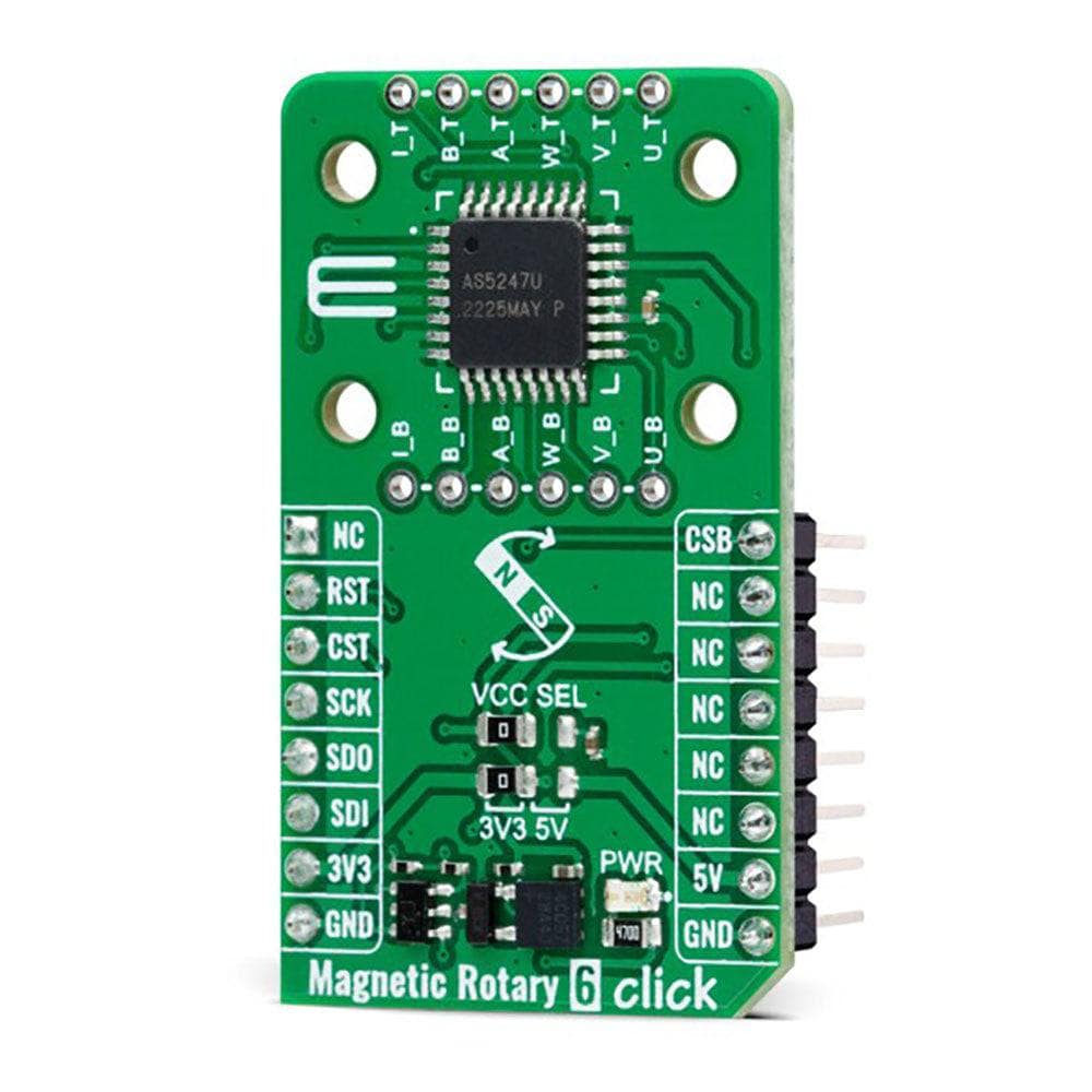
The Magnetic Rotary 6 Click Board™ is based on the AS5247U, a high-resolution dual rotary position sensor for fast absolute angle measurement over a full 360-degree range from ams AG. The core of the AS5247U represents a CMOS technology Hall-effect magnetic sensor that converts the magnetic field component perpendicular to the surface of the chip into a digital value. It supports high-speed applications up to 28krpm and allows a host MCU to read 14-bit absolute angle position data and to program non-volatile settings without a dedicated programmer. The AS5247U is also equipped with a Dynamic Angle Error Compensation block that corrects the calculated angle regarding latency by using a linear prediction calculation algorithm.
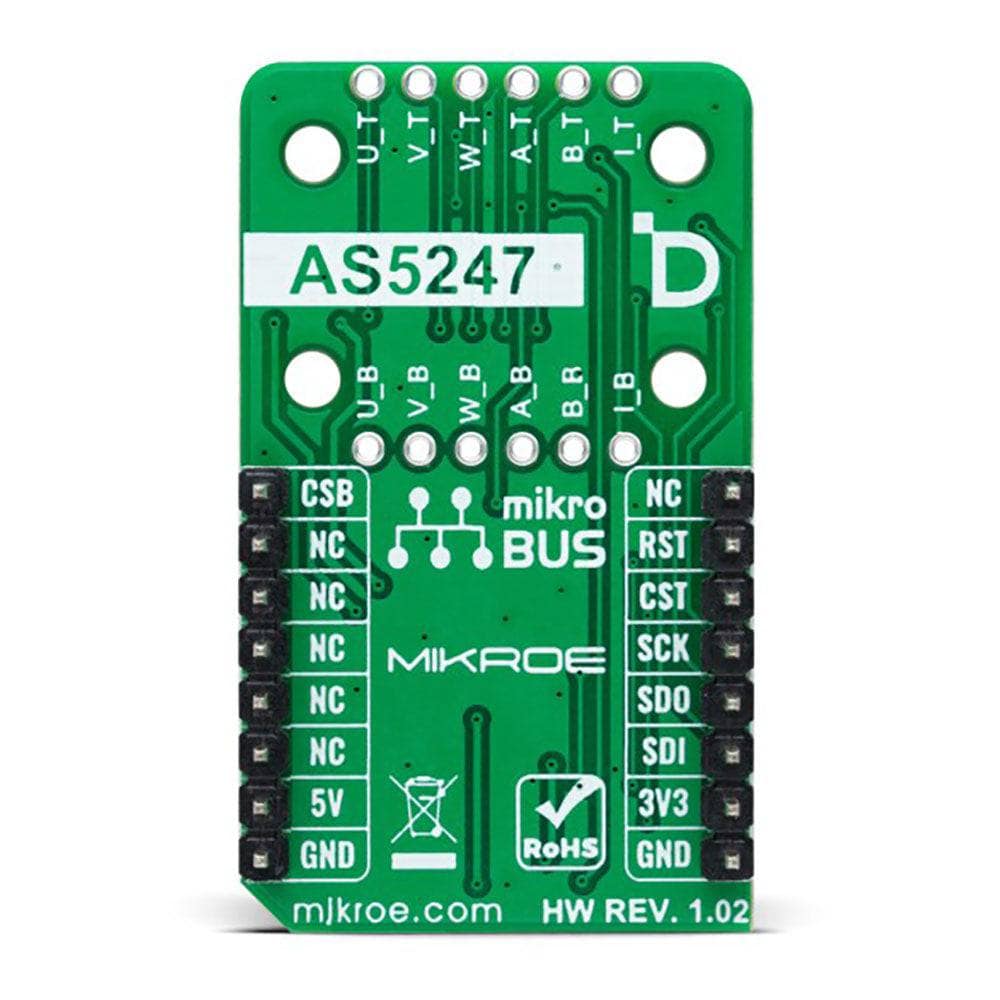
The AS5247U communicates with MCU using a standard SPI interface. The signals from its internal Hall sensors are amplified and filtered before their conversion by the ADC and then processed by the CORDIC block to compute the angle and magnitude of the magnetic field vector. The intensity of the magnetic field is used by the automatic gain control (AGC) to adjust the amplification level to compensate for temperature and magnetic field variations. This Click board™ also comes with onboard headers reserved for incremental and commutation signals of their respective A/B/I and U/V/W signals alongside embedded self-diagnostics. Incremental movements are indicated on a set of ABI signals with a maximum resolution of 16384 steps / 4096 pulses per revolution. The resolution of the ABI signal is programmable for 10 to 14 bits.
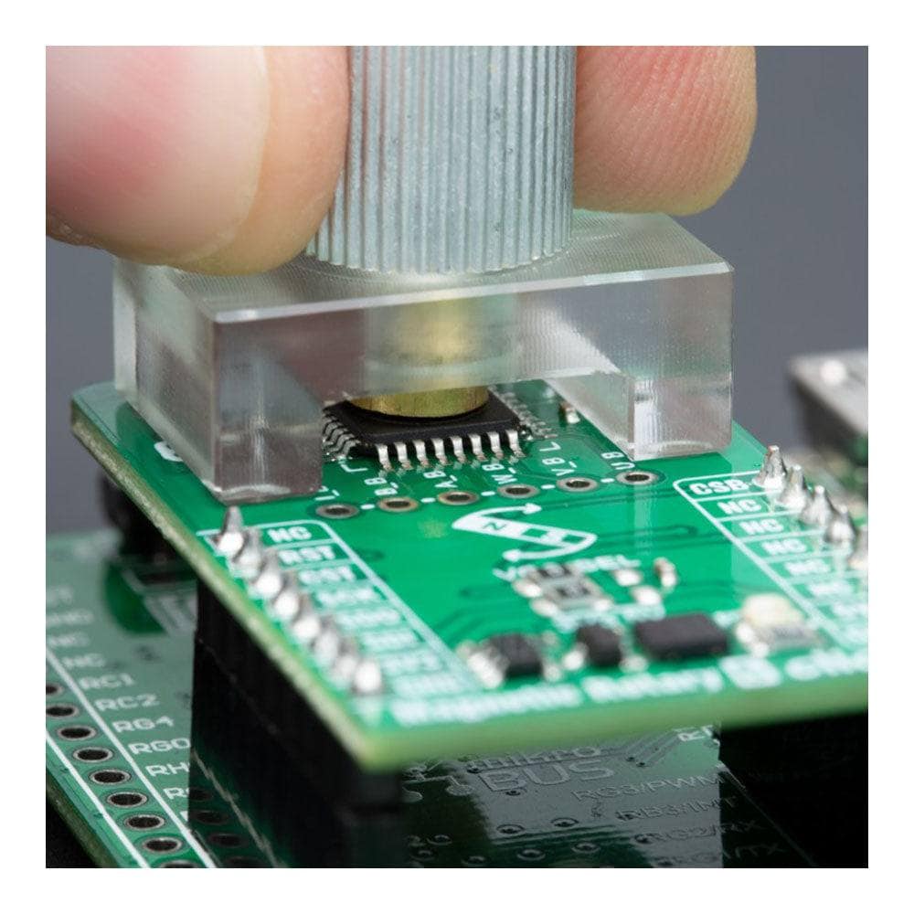
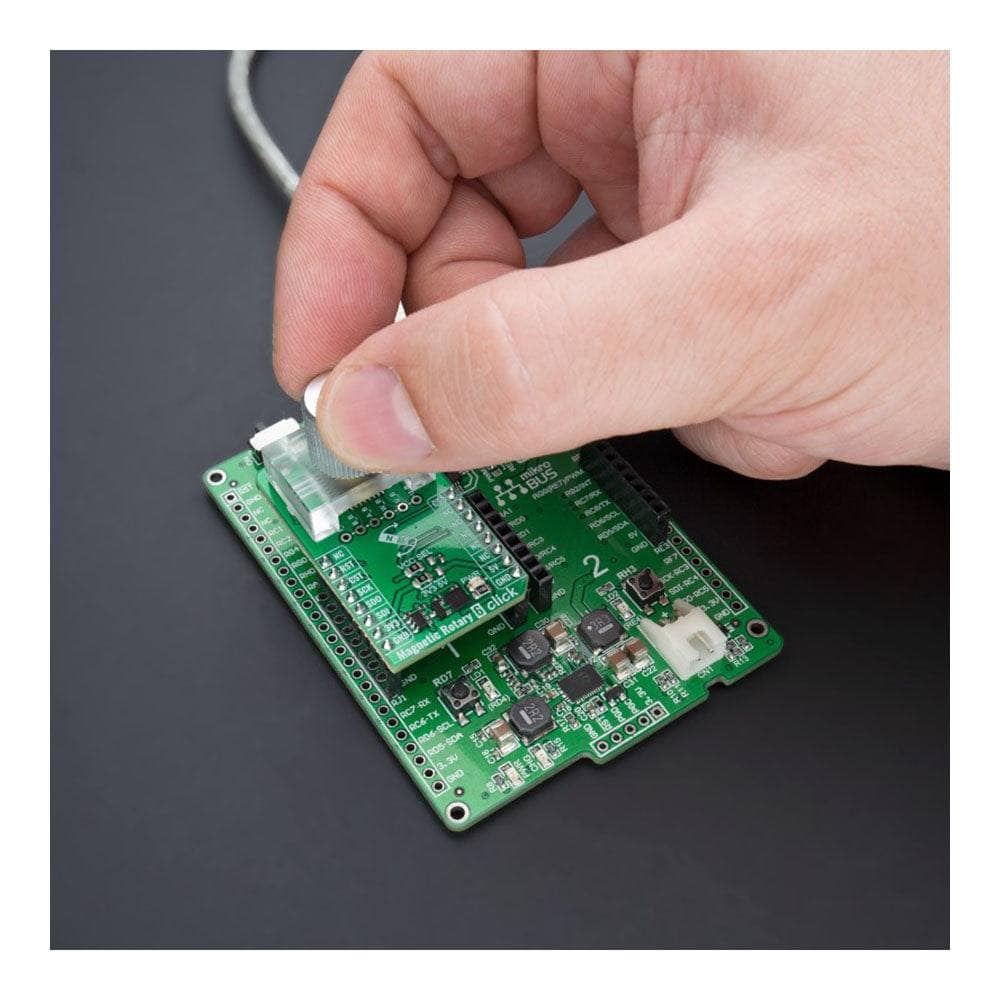
Brushless DC (BLDC) motors are also controllable through a standard UVW commutation interface with a programmable number of pole pairs from 1 to 7. At constant rotation speed, the latency time is internally compensated by the AS5247U, reducing the dynamic angle error at the SPI, ABI, and UVW outputs. The AS5047D also allows selection between a UVW output interface and a PWM-encoded interface on the W pin, which can be seen as an absolute angle position. A unique addition to this board is a position for a rotary magnet holder designed to be used alongside a magnetic rotary position sensor allowing fast prototyping and quick measurements during development.
Thie Magnetic Rotary 6 Click Board™ can operate with either 3.3V or 5V logic voltage levels selected via the VCC SEL jumper. All jumpers must be on the same side, or the Click board™ may become unresponsive. This way, both 3.3V and 5V capable MCUs can use the communication lines properly. However, the Click board™ comes equipped with a library containing easy-to-use functions and an example code that can be used, as a reference, for further development.
SPECIFICATIONS
| Type | Magnetic |
| Applications | Can be used to support BLDC motor commutation for the most challenging automotive and safety-critical applications |
| On-board modules | AS5247U - rotary position sensor for fast absolute angle measurement over a full 360-degree range from ams AG |
| Key Features | Good resolution for motor and position control, independent output interfaces, self-diagnostics, immune to external stray field, low power consumption, highest reliability and durability, rotary magnet holder, and more |
| Interface | SPI |
| Compatibility | mikroBUS |
| Click board size | M (42.9 x 25.4 mm) |
| Input Voltage | 3.3V or 5V |
PINOUT DIAGRAM
This table shows how the pinout of the Magnetic Rotary 6 Click Board™ corresponds to the pinout on the mikroBUS™ socket (the latter shown in the two middle columns).
| Notes | Pin | Pin | Notes | ||||
|---|---|---|---|---|---|---|---|
| NC | 1 | AN | PWM | 16 | CSB | External sync | |
| NC | 2 | RST | INT | 15 | NC | ||
| SPI Chip Select | CST | 3 | CS | RX | 14 | NC | |
| SPI Clock | SCK | 4 | SCK | TX | 13 | NC | |
| SPI Data OUT | SDO | 5 | MISO | SCL | 12 | NC | |
| SPI Data IN | SDI | 6 | MOSI | SDA | 11 | NC | |
| Power Supply | 3.3V | 7 | 3.3V | 5V | 10 | 5V | Power Supply |
| Ground | GND | 8 | GND | GND | 9 | GND | Ground |
ONBOARD SETTINGS AND INDICATORS
| Label | Name | Default | Description |
|---|---|---|---|
| LD1 | PWR | - | Power LED Indicator |
| JP1-JP2 | VCC SEL | Left | Logic Level Voltage Selection 3V3/5V: Left position 3V3, Right position 5V |
| J1-J2 | - | Unpopulated | Incremental and Commutation Signals Connection Header |
MAGNETIC ROTARY 6 CLICK ELECTRICAL SPECIFICATIONS
| Description | Min | Typ | Max | Unit |
|---|---|---|---|---|
| Supply Voltage | 3.3 | - | 5 | V |
| Rotation Angle Range | 0 | - | 360 | deg |
| Orthogonal Magnetic Field Strength | 35 | - | 70 | mT |
| Core Resolution | - | 14 | - | bit |
| ABI Resolution | 25 | - | 4096 | pulses |
| Maximum Speed | - | - | 28.000 | RPM |
Software Support
Software Support
We provide a library for the Magnetic Rotary 6 Click Board™ as well as a demo application (example), developed using MikroE compilers. The demo can run on all the main MikroE development boards.
The package can be downloaded/installed directly from NECTO Studio The package Manager (recommended), downloaded from our LibStock™ or found on MikroE Github account.
Library Description
This library contains API for the Magnetic Rotary 6 Click Board™ driver.
Key functions
-
magneticrotary6_write_registerThis function writes a desired data to the selected register of a desired sensor die by using SPI serial interface. -
magneticrotary6_get_angleThis function reads the absolute position raw data of a desired sensor die and converts it to degrees (Angle). -
magneticrotary6_set_directionThis function sets the rotation direction of a desired sensor die.
Example Description
This example demonstrates the use of the Magnetic Rotary 6 Click Board™ by reading and displaying the magnet's angular position in degrees measured by the bottom and top sensor dies.
void application_task ( void )
 {
     float angle;
     if ( MAGNETICROTARY6_OK == magneticrotary6_get_angle ( &magneticrotary6, MAGNETICROTARY6_DIE_BOTTOM, &angle ) )
     {
         log_printf( &logger, " Angle (bottom die): %.1f degreesrn", angle );
     }
     if ( MAGNETICROTARY6_OK == magneticrotary6_get_angle ( &magneticrotary6, MAGNETICROTARY6_DIE_TOP, &angle ) )
     {
         log_printf( &logger, " Angle (top die): %.1f degreesrnn", angle );
     }
     Delay_ms ( 100 );
 }
The full application code, and ready to use projects can be installed directly from NECTO Studio The package Manager (recommended), downloaded from our LibStock™ or found on MikroE Github account.
Other MikroE Libraries used in the example:
- MikroSDK.Board
- MikroSDK.Log
- Click.MagneticRotary6
Additional Notes and Information
Depending on the development board you are using, you may need USB UART Click Board™, USB UART 2 Click or RS232 Click to connect to your PC, for development systems with no UART to USB interface available on the board. A UART terminal is available in all MikroE compilers.
MIKROSDK
The Magnetic Rotary 6 Click Board™ is supported with mikroSDK - MikroE Software Development Kit, which needs to be downloaded from the LibStock and installed for the compiler you are using to ensure proper operation of mikroSDK compliant Click board™ demo applications.
Magnetic Rotary 6 Click Board
Frequently Asked Questions
Ask a Question-
What applications is the Magnetic Rotary 6 Click Board™ designed for?
The Click board™ has been designed to support BLDC motor commutation for the most challenging automotive and safety-critical applications.
-
Is the Magnetic Rotary 6 Click Board™ a fully tested product?
Yes, the Click board™ is a fully tested product and is ready to be used on a system equipped with the mikroBUS™ socket.
-
What is the mikroSDK compliant library?
The mikroSDK compliant library is a set of functions that simplify software development for the Magnetic Rotary 6 Click Board™.
-
What are the onboard headers reserved for?
The onboard headers are reserved for incremental and commutation signals of their respective A/B/I and U/V/W signals.
-
What is the maximum resolution of the Magnetic Rotary 6 Click Board™?
The maximum resolution of the Click board™ is 16384 steps/4096 pulses per revolution.
-
What is dynamic angle error compensation (DAEC™)?
DAEC™ is a revolutionary integrated feature of the AS5047D that compensates for any dynamic angle errors in the sensor output with almost zero latency.
-
What is the AS5247U?
The AS5247U is a high-resolution dual rotary position sensor from ams AG that is SPI-configurable and allows for fast absolute angle measurement over a full 360-degree range.
-
What is the Magnetic Rotary 6 Click Board™?
The Magnetic Rotary 6 Click Board™ is a compact add-on board that allows for accurate magnet-position sensing. It is equipped with the AS5247U, an SPI-configurable high-resolution dual rotary position sensor for fast absolute angle measurement over a full 360-degree range from ams AG.