


Mikroelektronika d.o.o.
SKU: MIKROE-5574USB UART 5 Click Board
USB UART 5 Click Board
Couldn't load pickup availability
Key Features
- HID interface USB to UART data transfer, full speed USB 2.0-compliant, standard USB class device that requires no custom driver, Self or USB powered configuration, UART flow control, various data formats and baud rates, RS-485 mode with bus transceiver control, Suspend mode, GPIO interface, and more
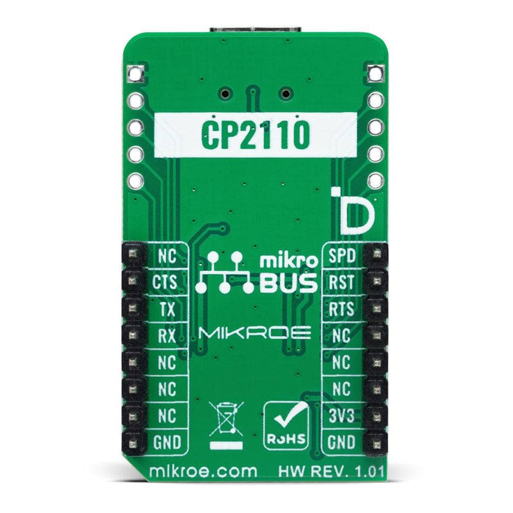
- Based on the CP2110 - USB-to-UART bridge controller from Silicon Labs
- Can be used to quickly add a USB 2.0 full-speed compliant UART interface for custom applications
- mikroBUS: UART Interface and USB Type-C
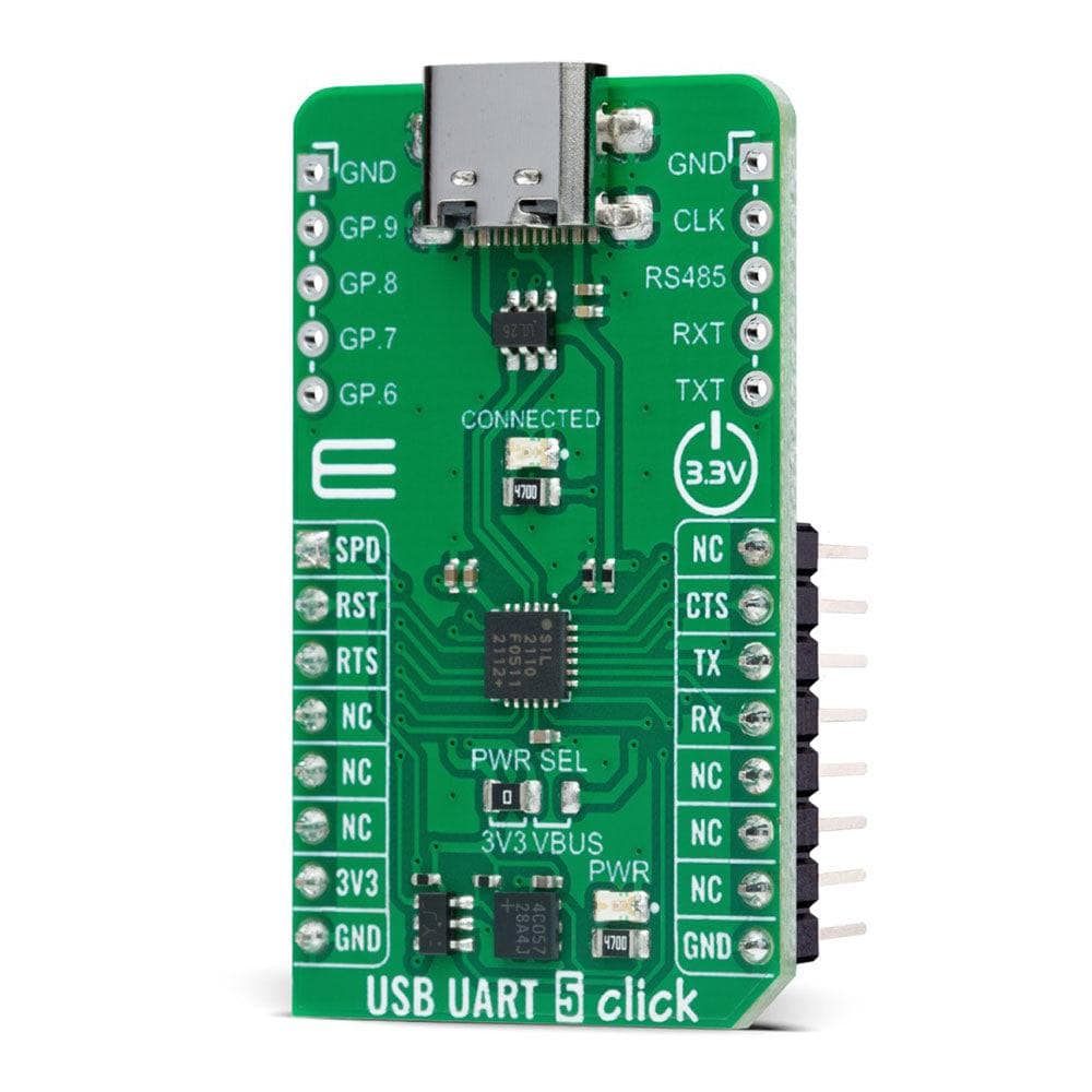
Introducing the USB UART 5 Click Board™
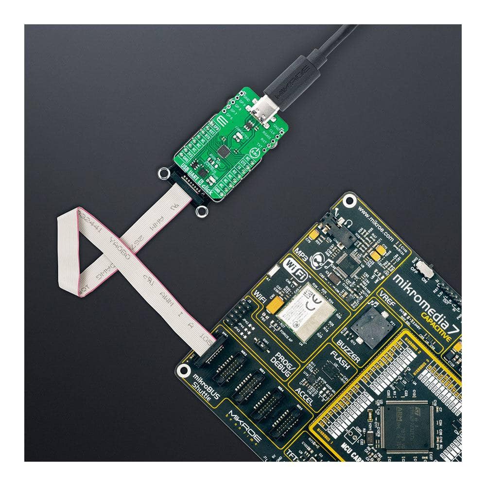
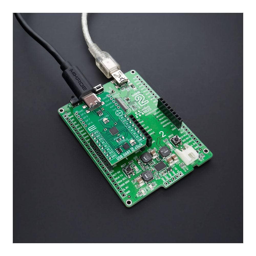
Looking for a compact and easy-to-use add-on board with a general-purpose USB to UART serial interface? Look no further than the USB UART 5 Click Board™. Featuring the highly-integrated CP2110 USB-to-UART bridge controller from Silicon Labs, this board offers a range of impressive features and benefits that make it an ideal choice for a wide variety of custom applications.
Powerful Features and Capabilities
The CP2110 uses the standard USB HID device class, meaning that no custom driver is required. In addition, the UART interface implements all RS-232 signals, including control and hardware handshaking, so existing system firmware does not need to be modified. The UART capabilities of the CP2110 include baud rate support from 300 to 1Mbps, hardware flow control, RS-485 support, and GPIO signals that are user-defined for status and control information.
Easy to Use and Implement
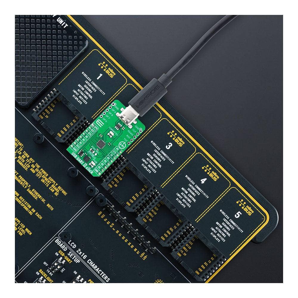
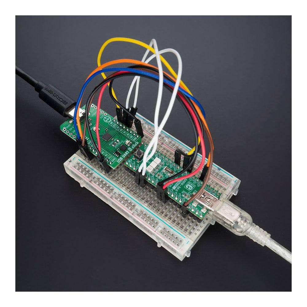
Designed to quickly add a USB 2.0 full-speed compliant UART interface for custom applications, the USB UART 5 Click Board™ is easy to use and implement. Plus, it is supported by a mikroSDK compliant library that includes functions to simplify software development. And, as a fully tested product, it is ready to be used on a system equipped with the mikroBUS™ socket.
Get started with the USB UART 5 Click Board™ today and experience the power and convenience of this compact and versatile add-on board!

How Does The USB UART 5 Click Board™ Work?
The USB UART 5 Click Board™ is based on the CP2110, a single-chip HID USB to UART bridge controller from Silicon Labs. A USB function controller in the CP2110 is a USB 2.0-compliant, full-speed device with an integrated USB transceiver, one-time programmable ROM, and an asynchronous serial data bus (UART) in one compact package. The UART capabilities of the CP2110 include baud rate support from 300 to 1Mbps, hardware flow control, RS-485 support, and GPIO signals that are user-defined for status and control information. The USB function controller manages all data transfers between USB and UART, command requests generated by the USB host controller, and commands for controlling the function of the UARTs and GPIO pins.
The CP2110 uses the standard USB HID device class, natively supported by most operating systems. A custom driver does not need to be installed for this device. In addition, the CP2110 also supports USB Suspend and Resume modes for power management purposes. The CP2110 enters Suspend mode when Suspend signaling is detected on the bus using the SPD pin of the mikroBUS™ socket. Upon entering Suspend mode, the SPD signal is asserted, but it can also be asserted after a reset condition (RST pin) until device configuration during USB Enumeration is complete. SPD pin detects logic high level when the device is in the Suspend state and logic low when the device is in Normal mode, which is also visually indicated via red LED labelled as CONNECTED.
The USB UART 5 Click Board™ also features 8 GPIO signals, located on unpopulated headers, that are user-defined for status and control information. Four GPIO signals support alternate features, including a configurable clock output (CLK) from 24MHz to 47kHz, RS-485 transceiver control, and TX and RX LED toggle features. Also, the USB UART 5 Click can work in a USB-powered configuration thanks to the ability of the CP2110 to provide adequate power to all its parts with the help of an internal regulator using the USB bus voltage. To select this mode of operation, it is necessary to switch the jumper PWR SEL to the position marked with VBUS.
The USB UART 5 Click Board™ can only be operated from a 3.3V logic voltage level. Therefore, the board must perform appropriate logic voltage conversion before using MCUs with different logic levels. However, the Click board™ comes equipped with a library containing functions and an example code that can be used as a reference for further development.
SPECIFICATIONS
| Type | USB |
| Applications | Can be used to quickly add a USB 2.0 full-speed compliant UART interface for custom applications |
| On-board modules | CP2110 - USB-to-UART bridge controller from Silicon Labs |
| Key Features | HID interface USB to UART data transfer, full speed USB 2.0-compliant, standard USB class device that requires no custom driver, Self or USB powered configuration, UART flow control, various data formats and baud rates, RS-485 mode with bus transceiver control, Suspend mode, GPIO interface, and more |
| Interface | UART,USB |
| Compatibility | mikroBUS |
| Click board size | M (42.9 x 25.4 mm) |
| Input Voltage | 3.3V or 5V |
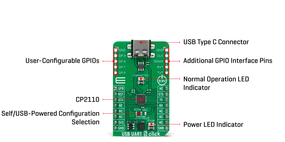
PINOUT DIAGRAM
This table shows how the pinout of the USB UART 5 Click Board™ corresponds to the pinout on the mikroBUS™ socket (the latter shown in the two middle columns).
| Notes | Pin | Pin | Notes | ||||
|---|---|---|---|---|---|---|---|
| Suspend Mode | SPD | 1 | AN | PWM | 16 | NC | |
| Reset | RST | 2 | RST | INT | 15 | CTS | UART CTS |
| UART RTS | RTS | 3 | CS | RX | 14 | TX | UART TX |
| NC | 4 | SCK | TX | 13 | RX | UART RX | |
| NC | 5 | MISO | SCL | 12 | NC | ||
| NC | 6 | MOSI | SDA | 11 | NC | ||
| Power Supply | 3.3V | 7 | 3.3V | 5V | 10 | NC | |
| Ground | GND | 8 | GND | GND | 9 | GND | Ground |
ONBOARD SETTINGS AND INDICATORS
| Label | Name | Default | Description |
|---|---|---|---|
| LD1 | PWR | - | Power LED Indicator |
| LD2 | CONNECTED | - | Normal Operation LED Indicator |
| JP1 | PWR SEL | Left | Self/USB-Powered Configuration Selection 3V3/VBUS: Left position 3V3, Right position VBUS |
| J1-J2 | - | Unpopulated | User-Configurable GPIOs Headers |
USB UART 5 CLICK ELECTRICAL SPECIFICATIONS
| Description | Min | Typ | Max | Unit |
|---|---|---|---|---|
| Supply Voltage | - | 3.3 | - | V |
| Baud Rate | 0.0003 | - | 1 | Mbps |
| Configurable Clock Output | 47 | - | 24.000 | kHz |
Software Support
We provide a library for the USB UART 5 Click Board™ as well as a demo application (example), developed using MikroE compilers. The demo can run on all the main MikroE development boards.
The package can be downloaded/installed directly from NECTO Studio The package Manager (recommended), downloaded from our LibStock™ or found on MikroE Github account.
Library Description
This library contains API for the USB UART 5 Click Board™ driver.
Key functions
-
usbuart5_generic_writeUSB UART 5 data writing function. -
usbuart5_generic_readUSB UART 5 data reading function. -
usbuart5_reset_deviceUSB UART 5 reset the device function.
Example Description
This example reads and processes data from the USB UART 5 Click Board™. The library initializes and defines the UART bus drivers to transmit or receive data.
void application_task ( void )
{
    char rx_data = 0;
    if ( usbuart5_generic_read ( &usbuart5, &rx_data, 1 ) )
    {
        if ( usbuart5_generic_write ( &usbuart5, &rx_data, 1 ) )
        {
            log_printf( &logger, "%c", rx_data );
        }
    }
}
The full application code, and ready to use projects can be installed directly from NECTO Studio The package Manager (recommended), downloaded from our LibStock™ or found on MikroE Github account.
Other MikroE Libraries used in the example:
- MikroSDK.Board
- MikroSDK.Log
- Click.USBUART5
Additional Notes and Information
Depending on the development board you are using, you may need USB UART Click, USB UART 2 Click, or RS232 Click to connect to your PC for development systems with no UART to USB interface available on the board. A UART terminal is available in all MikroE compilers.
MIKROSDK
A mikroSDK supports the UUSB UART 5 Click Board™ - MikroE Software Development Kit, which needs to be downloaded from the LibStock and installed for the compiler you are using to ensure proper operation of mikroSDK compliant Click board™ demo applications.
USB UART 5 Click Board
Frequently Asked Questions
Ask a Question-
What applications is the USB UART 5 Click Board™ suitable for?
The USB UART 5 Click Board™ is suitable for a wide variety of custom applications, thanks to its powerful features and capabilities. It is an ideal choice for anyone looking for a compact and versatile add-on board with a general-purpose USB to UART serial interface.
-
Is the USB UART 5 Click Board™ easy to use?
Yes, the USB UART 5 Click Board™ is designed to be easy to use and implement. It is supported by a mikroSDK compliant library that includes functions to simplify software development. As a fully tested product, it is ready to be used on a system equipped with the mikroBUS™ socket.
-
What are the features and capabilities of the CP2110?
The CP2110 offers a range of impressive features and capabilities, including baud rate support from 300 to 1Mbps, hardware flow control, RS-485 support, and GPIO signals that are user-defined for status and control information. The UART interface implements all RS-232 signals, including control and hardware handshaking.
-
What is the CP2110 USB-to-UART bridge controller?
The CP2110 is a highly-integrated USB-to-UART bridge controller from Silicon Labs. It uses the standard USB HID device class, meaning that no custom driver is required.
-
What is the USB UART 5 Click Board™?
The USB UART 5 Click Board™ is a compact and easy-to-use add-on board that features a general-purpose USB to UART serial interface. It is designed to quickly add a USB 2.0 full-speed compliant UART interface for custom applications.