Key Features
Overview
Introducing the LED Driver 17 Click Board™ - The Ultimate Solution for LED Control
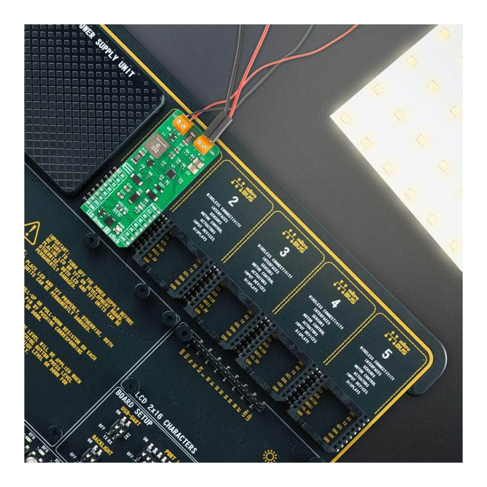
Discover the LED Driver 17 Click Board™, a compact and versatile add-on board that offers a simple yet powerful solution for controlling multiple LEDs in various applications. Whether you're working on architectural lighting, general lighting, or just exploring your creativity with LEDs, this is the perfect choice for you!
Featuring the LTR3755 - A High-Efficiency DC/DC Controller from Analog Devices
At the heart of this remarkable board is the LTR3755, a highly efficient DC/DC controller designed to operate as a constant-current source. With the ability to easily drive high-current LEDs and onboard low-side external N-channel power MOSFETs, the LED Driver 17 Click Board™ ensures stable operation over a wide supply range.
Comprehensive LED Protection Features
Designed with user safety in mind, the LED Driver 17 Click Board™ offers several essential protection features for your LEDs, including overvoltage and overcurrent protection. Plus, the frequency adjust pin allows you to program the switching frequency from 100kHz to 1MHz, optimizing efficiency and performance to suit your needs.
Supported by mikroSDK - Simplifying Software Development
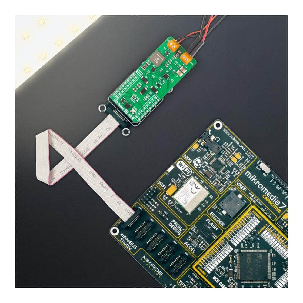
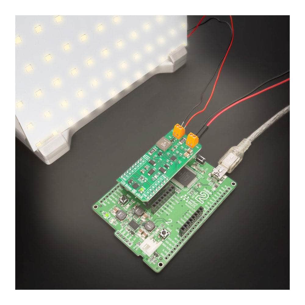
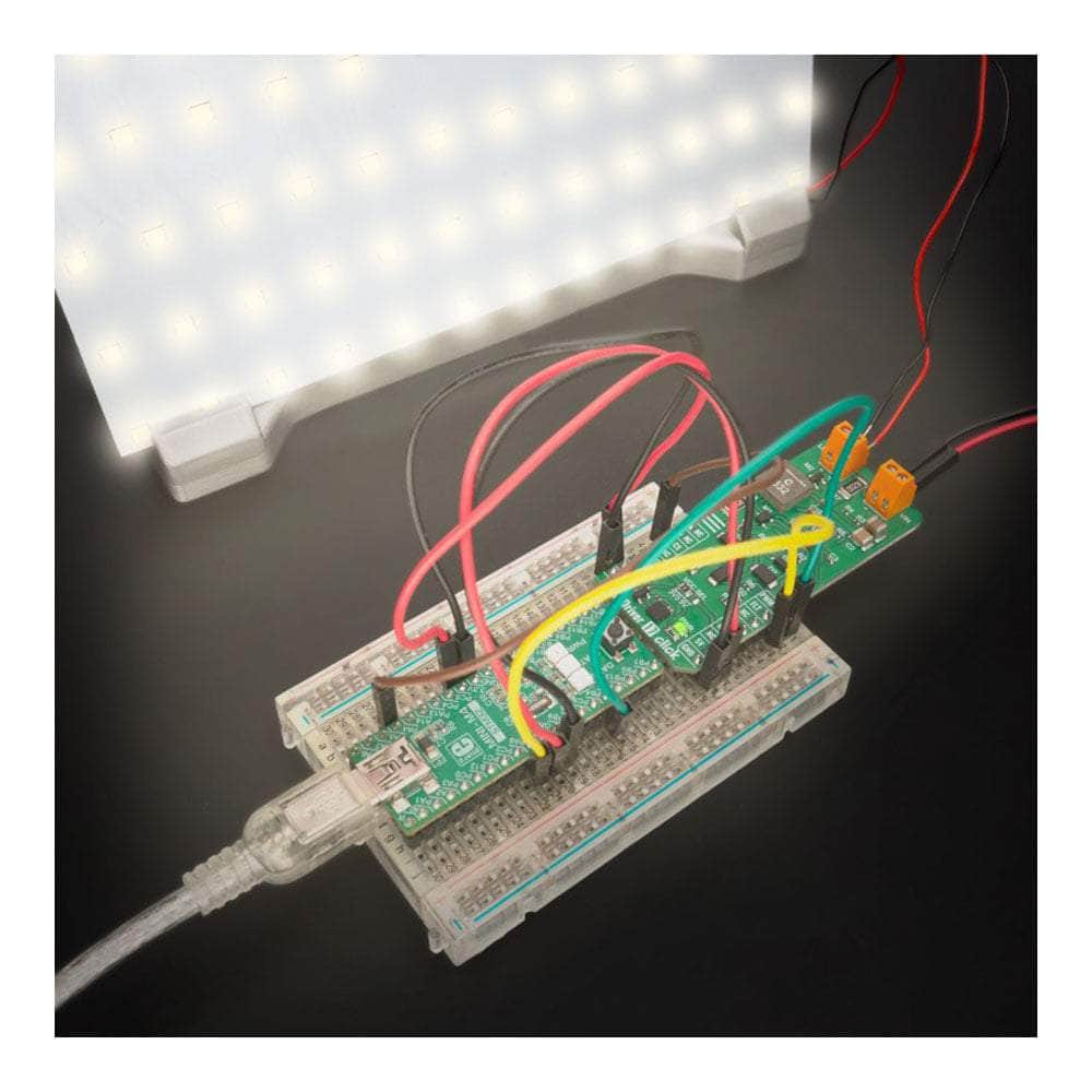
When it comes to software development, the LED Driver 17 Click Board™ has you covered. It is supported by a mikroSDK-compliant library, which includes functions that make software development a breeze. This Click board™ comes as a fully tested product, ready to be integrated into any system equipped with the mikroBUS™ socket.
A Versatile Choice for Hobbyists and Professionals Alike
Whether you're a hobbyist or a professional, the LED Driver 17 Click Board™ is the ideal choice for controlling multiple LEDs in various settings. With its comprehensive features, ease of use, and reliable performance, this Click board™ will undoubtedly enhance your LED projects and applications.
Downloads
How Does The LED Driver 17 Click Board™ Work?
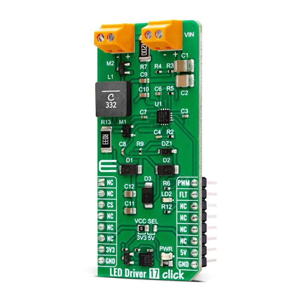
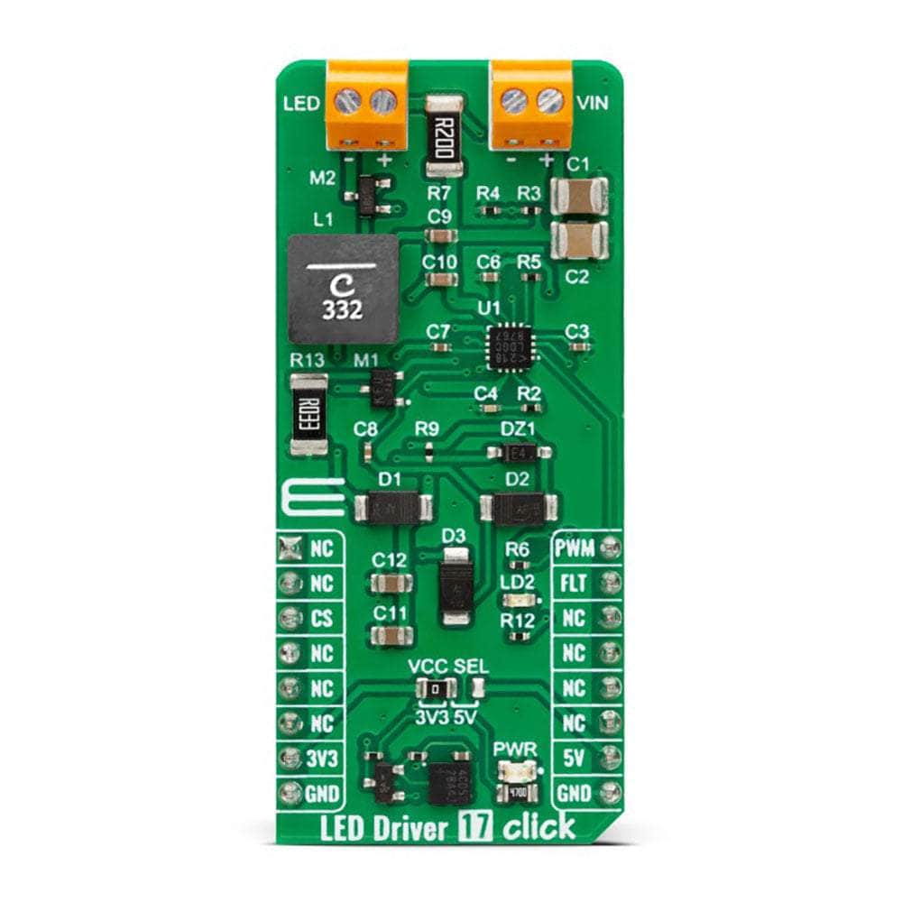
The LED Driver 17 Click Board™ is based on the LT3755, a highly efficient DC/DC controller from Analog Devices. This Click board™ is designed as a Buck mode LED driver with the ability to output 500mA, offering, in addition, PWM dimming functionality. The LTR3755, a highly efficient DC/DC controller, operates as a constant-current source, features onboard low-side external N-channel power MOSFETs, which are driven from an internal regulated supply, and it is capable of driving high-power 16V LEDs. Due to its high efficiency and reliable protection features, this board can be used in applications that require consistent and precise LED lighting control. It can also be used in applications that demand high power output, such as commercial and industrial lighting.
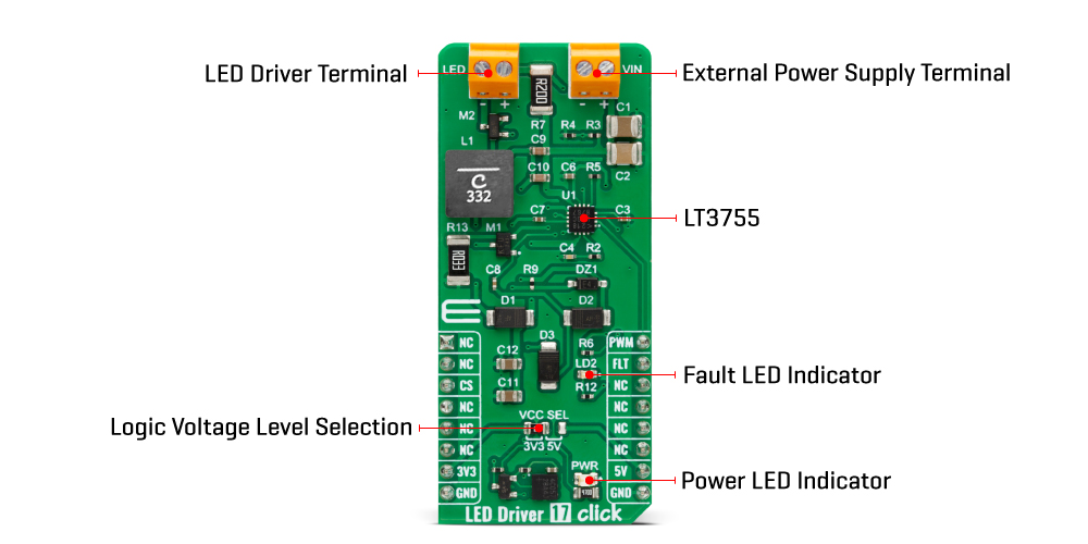
In terms of connectivity, this solution is designed to be controlled via the PWM pin of the mikroBUS™ socket to provide LED dimming control with ratios of up to 3000:1. In addition, the LT3755 also has a frequency adjust pin that allows the user to program the switching frequency from 100kHz to 1MHz. This feature is performed via an onboard R5 resistor, with the 800kHz set as the default value to optimize efficiency and performance.
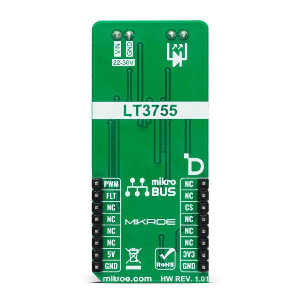
Besides the PWM pin, this Click board™ also features a fault pin labelled FLT, which is routed to the default interrupt INT position of the mikroBUS™ socket. This fault pin indicates any fault conditions to an external system, including overvoltage and overcurrent protection. Besides information via the mikroBUS™ socket, the fault signal is visually indicated via a red LED labelled LD2. This LED Driver 17 Click supports an external power supply for the driver, which can be connected to the input terminal labelled VIN and should be within the range of 22V to 36V.
The LED Driver 17 Click Board™ can operate with either 3.3V or 5V logic voltage levels selected via the VCC SEL jumper. This way, both 3.3V and 5V capable MCUs can use the communication lines properly. However, the Click board™ comes equipped with a library containing easy-to-use functions and an example code that can be used, as a reference, for further development.
SPECIFICATIONS
| Type | LED Drivers |
| Applications | It can be used for applications that demand high power output, such as commercial and industrial lighting |
| On-board modules | LTR3755 - DC/DC controller from Analog Devices |
| Key Features | Buck mode LED driver, 500mA, PWM dimming, wide input voltage supply, output voltage suitable for 16V high power LEDs, protection features, adjustable switching frequency, fault detection and indication, and more |
| Interface | PWM |
| Compatibility | mikroBUS |
| Click board size | L (57.15 x 25.4 mm) |
| Input Voltage | 3.3V or 5V |
PINOUT DIAGRAM
This table shows how the LED Driver 17 Click Board™ pinout corresponds to the pinout on the mikroBUS™ socket (the latter is shown in the two middle columns).
| Notes | Pin |  |
Pin | Notes | |||
|---|---|---|---|---|---|---|---|
| NC | 1 | AN | PWM | 16 | PWM | PWM Signal | |
| NC | 2 | RST | INT | 15 | FLT | Fault Signal | |
| NC | 3 | CS | RX | 14 | NC | ||
| NC | 4 | SCK | TX | 13 | NC | ||
| NC | 5 | MISO | SCL | 12 | NC | ||
| NC | 6 | MOSI | SDA | 11 | NC | ||
| Power Supply | 3.3V | 7 | 3.3V | 5V | 10 | 5V | Power Supply |
| Ground | GND | 8 | GND | GND | 9 | GND | Ground |
ONBOARD SETTINGS AND INDICATORS
| Label | Name | Default | Description |
|---|---|---|---|
| LD1 | PWR | - | Power LED Indicator |
| LD2 | LD2 | - | Fault LED Indicator |
| JP1 | VCC SEL | Left | Logic Level Voltage Selection 3V3/5V: Left position 3V3, Right position 5V |
LED DRIVER 17 CLICK ELECTRICAL SPECIFICATIONS
| Description | Min | Typ | Max | Unit |
|---|---|---|---|---|
| Supply Voltage | 3.3 | - | 5 | V |
| Input Voltage Range | 22 | - | 36 | V |
| Output Current | - | 500 | - | mA |
| General Information | |
|---|---|
Part Number (SKU) |
MIKROE-5565
|
Manufacturer |
|
| Physical and Mechanical | |
Weight |
0.02 kg
|
| Other | |
Country of Origin |
|
HS Code Customs Tariff code
|
|
EAN |
8606027384936
|
Warranty |
|
Frequently Asked Questions
Have a Question?
Be the first to ask a question about this.

