Collection: MikroE Click Boards™
Add Versatility and Expandability with MikroElektronika Click Boards™
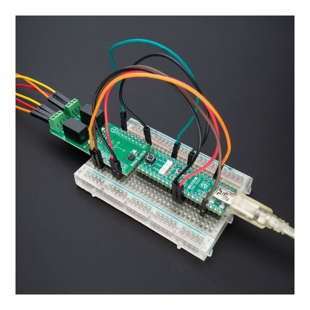
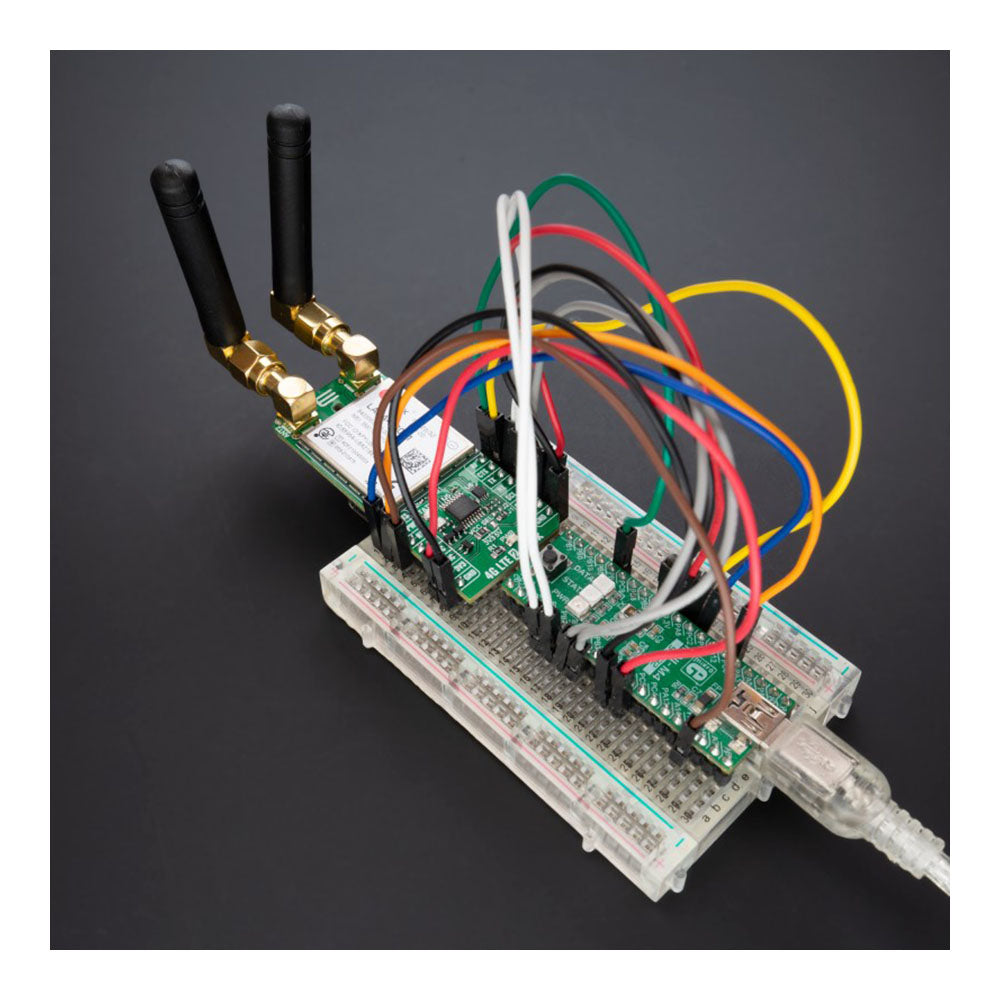
MikroElektronika Click BoardsTM are compact, production-ready add-on boards that provide versatile functionality for rapid prototyping and development.
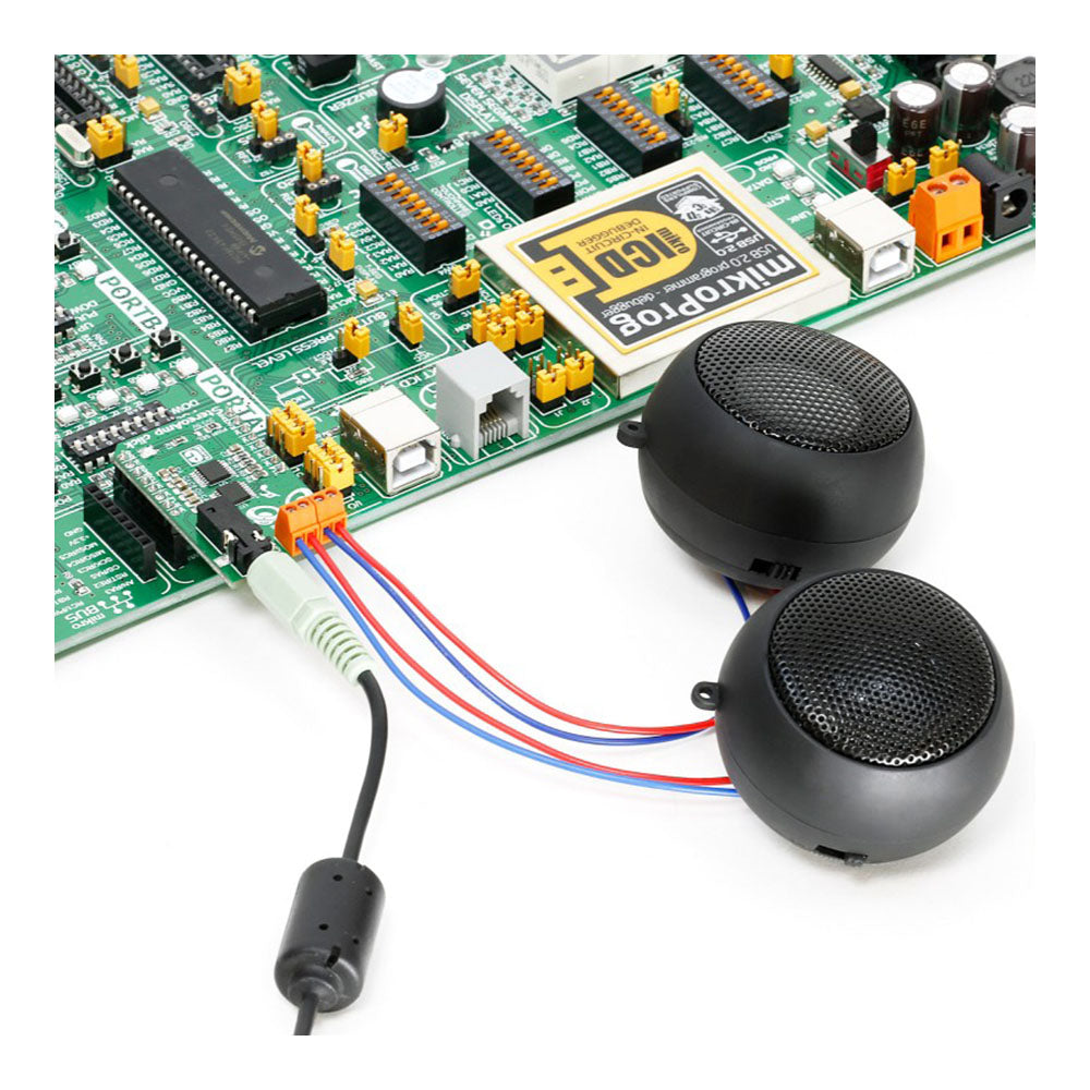
Daughter Board Design for Seamless Integration
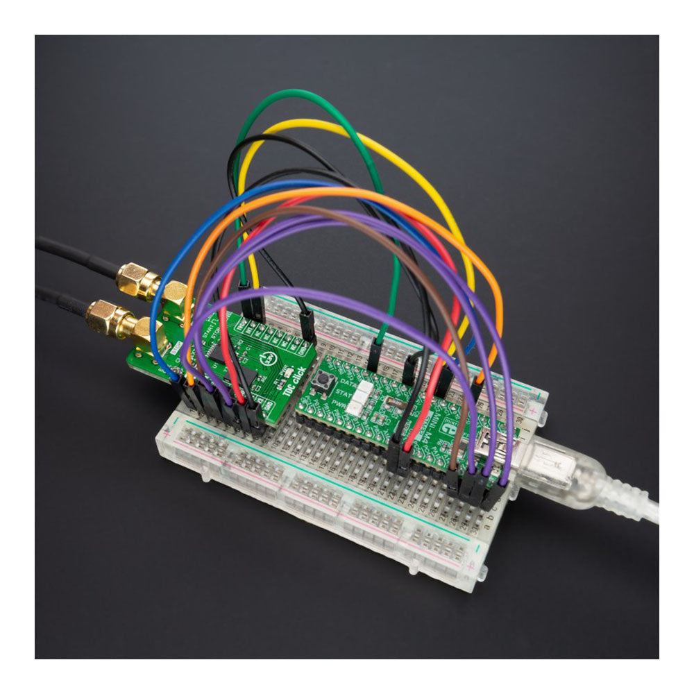
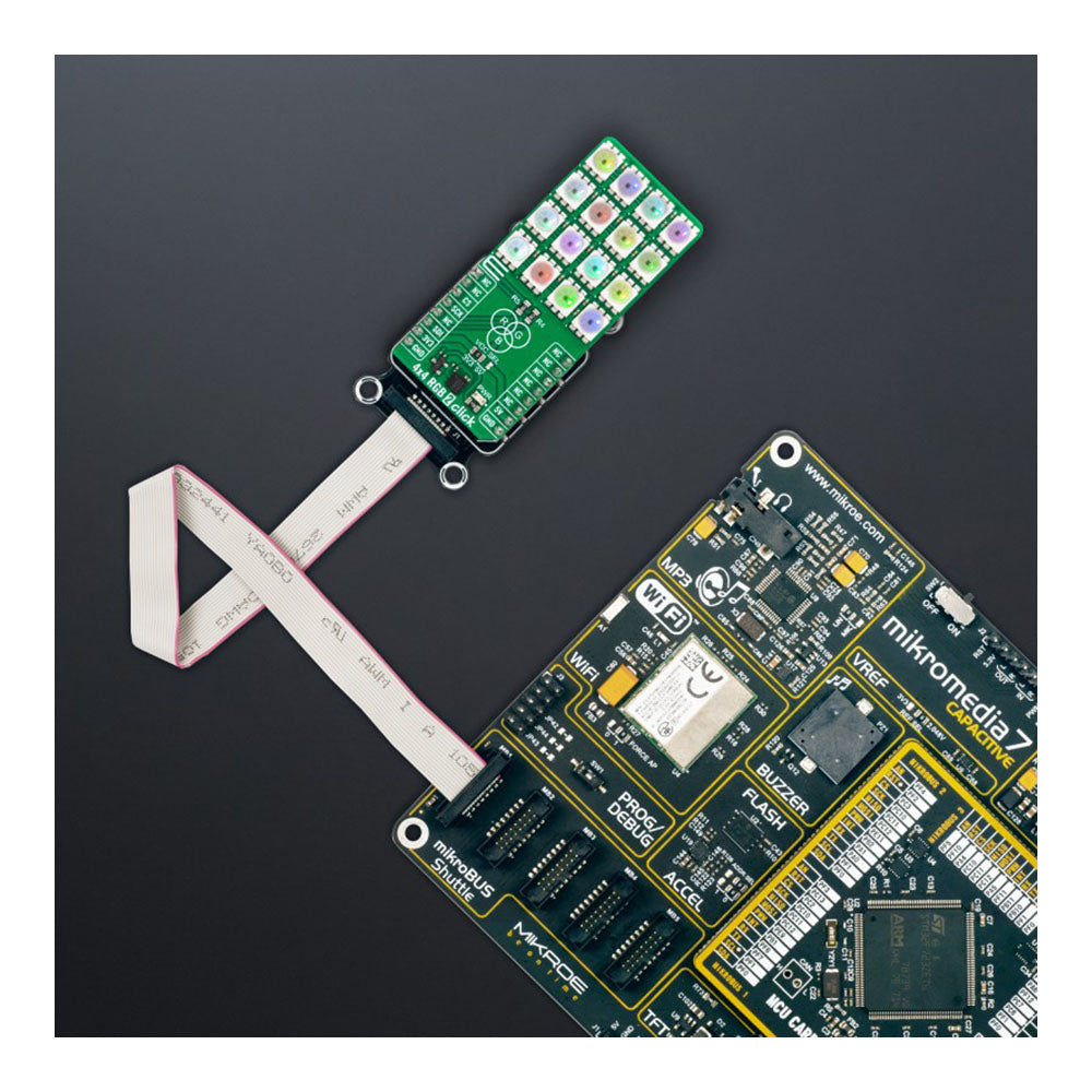
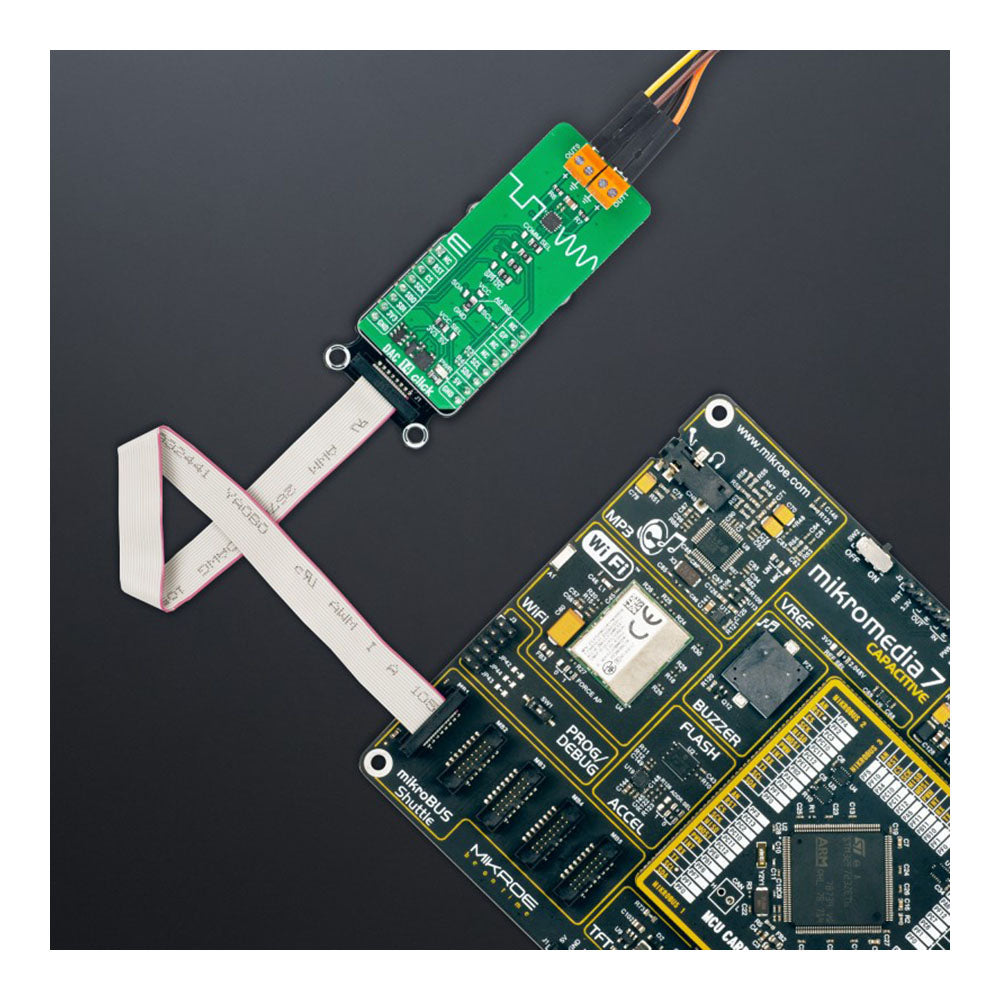
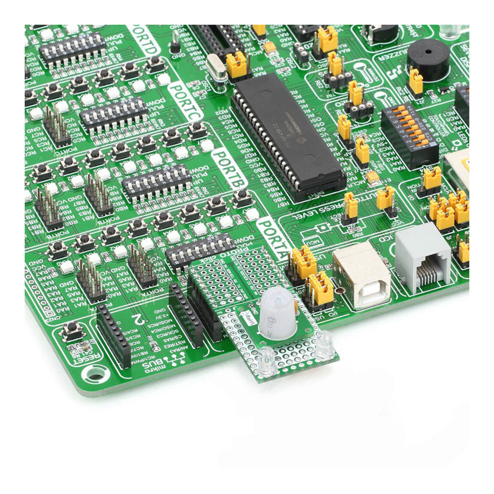
Click Boards™ feature a standardized daughterboard design plugs directly into MikroElektronika development boards via the mikroBUSTM socket. This allows for quick set-up and easy expansion without wiring or soldering. Plug in a Click Board™ and start developing.
Over 1,500 Options for Limitless Possibilities
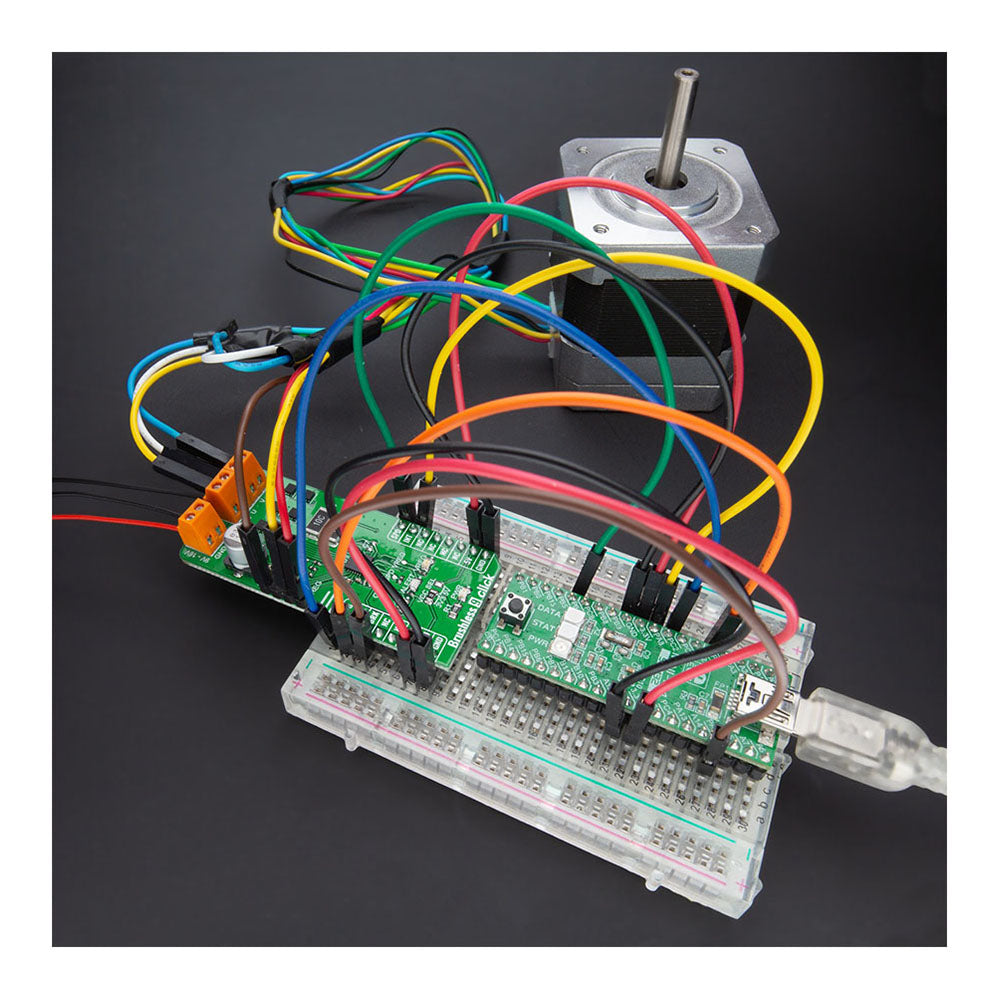
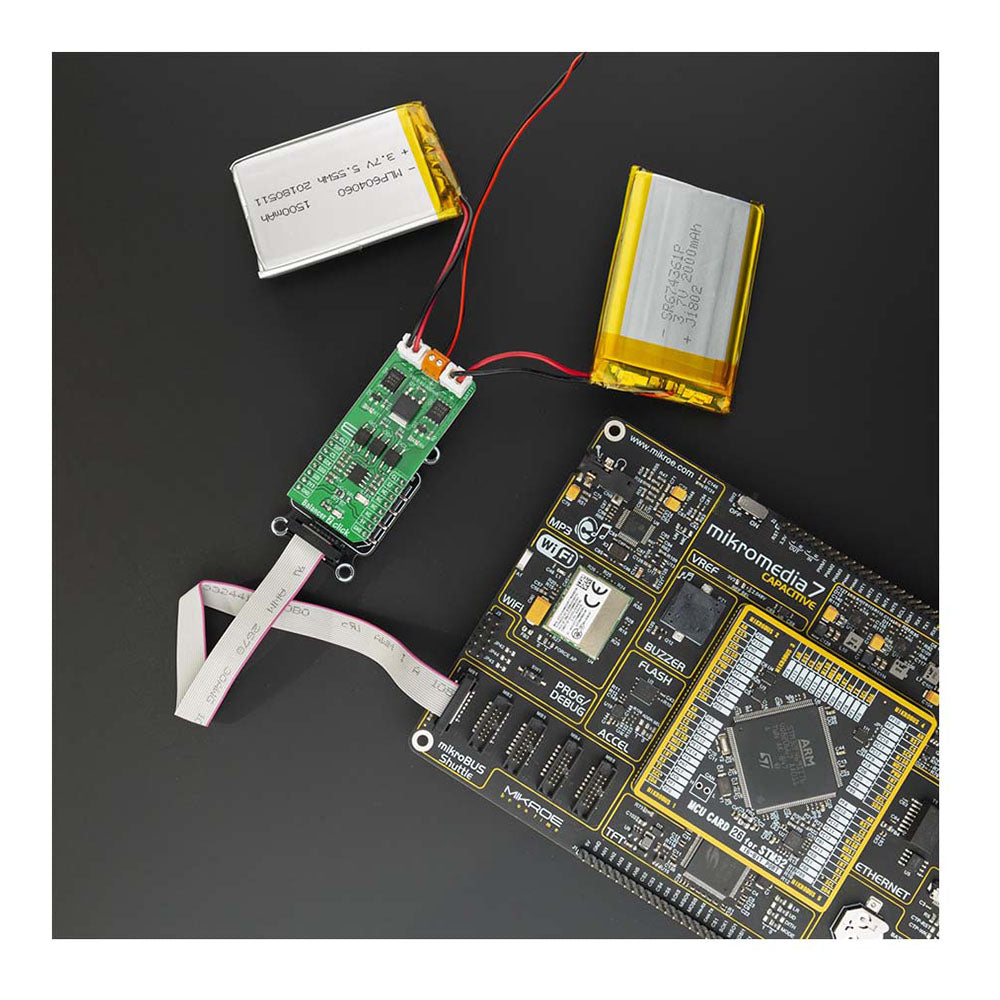
With over 1000 Click Boards™ available, the options are virtually limitless. Choose from boards featuring wireless connectivity, sensors, displays, motor drivers, etc. Mix and match Click Boards™ to create customized solutions for your needs.
Complete Support for Rapid Development
All Click Boards™ come with full software support in MikroElektronika compilers and mikroSDK. Example code and libraries simplify software development so you can focus on programming the essential functions.
-
Audio & Voice Click Boards™
Audio & Voice Click Boards from MikroE, available at Debug Store, are...
-
Clock & Timing Click Boards™
Discover a world of precise timing solutions with our Clock & Timing...
-
Display & Interface Click Boards™
Our MikroE Display & Interface Click Boards™ collection encompasses a variety of...
-
HMI Interface Click Boards™
Our MikroE HMI Interface Click Boards™ are designed to enhance the user...
-
Memory Device Click Boards™
Memory Click Boards™ - Enhance Your Project's Data Storage and Processing Welcome...
-
Miscellaneous Click Boards™
Welcome to The Debug Store's collection of Miscellaneous MikroE Click Boards™! Our...
-
Mixed Signal Click Boards™
Click boards that convert analogue quantities to digital and vice versa are...
-
Motor Control Click Boards™
MikroE Motor Control Click Boards™ are powerful and versatile motor control solutions...
-
Power Management Click Boards™
MikroElektronika's power management Click Boards™, available at Debug Store, offer efficient solutions...
-
Prototype Click Boards™
Quickly develop your own Click Board™ with a Prototype Click Board™. It...
-
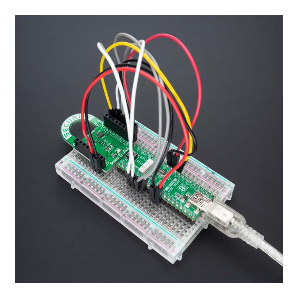
Security Click Boards™
Welcome to The Debug Store, your ultimate destination for top-of-the-line MikroE Security...
-
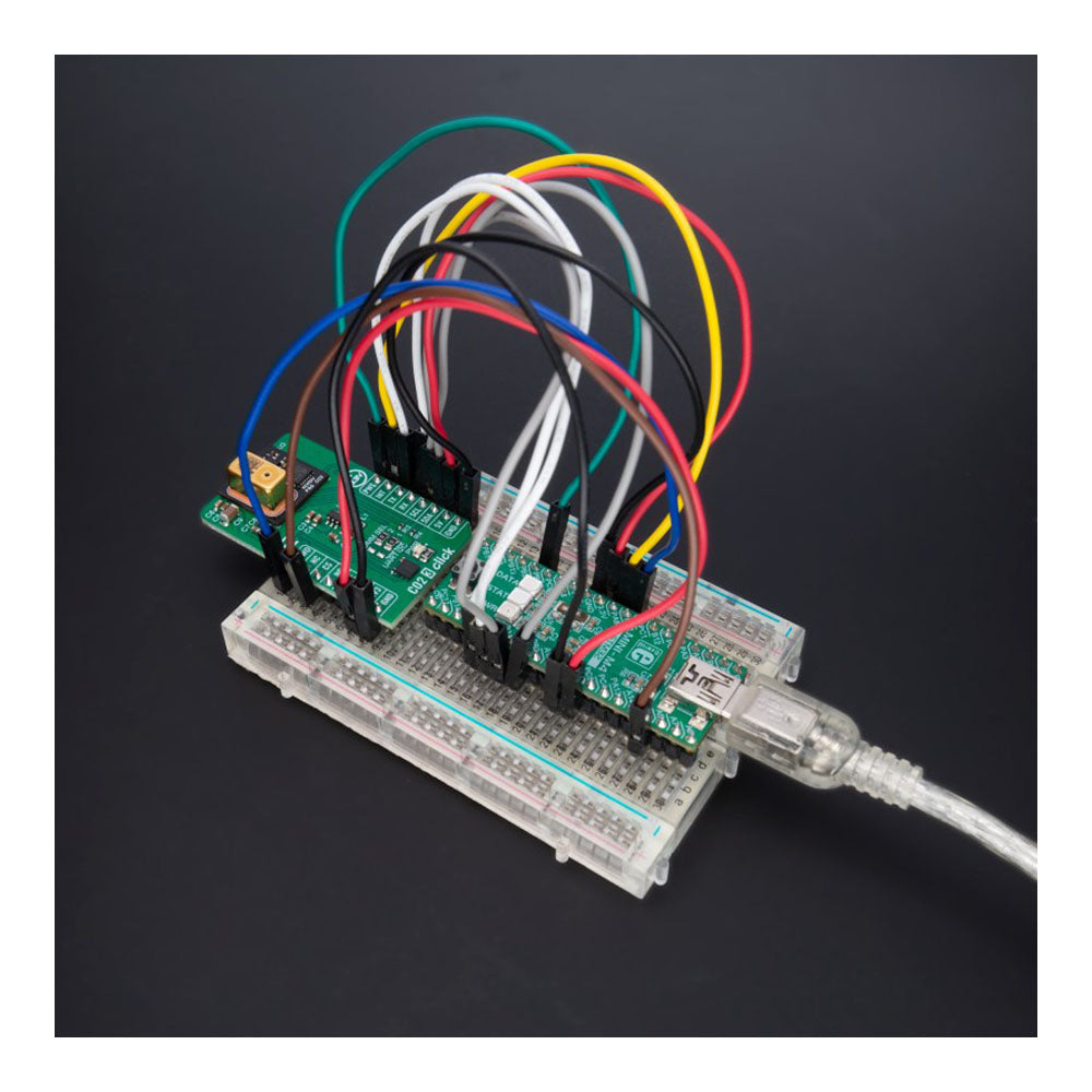
Sensor Click Boards™
Whether you're an electronics enthusiast or a professional developer, our Sensor Click...
-
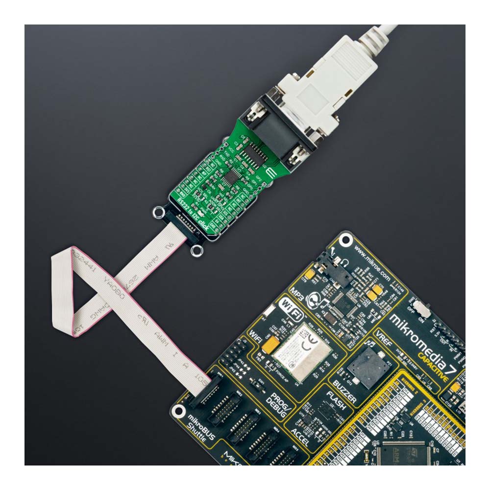
Serial Interface Click Boards™
MikroE's serial interface Click Boards offer a versatile range of add-on modules...
-
Wireless Interface Click Boards™
Whether you're working on IoT applications, smart home devices, or industrial automation...


-
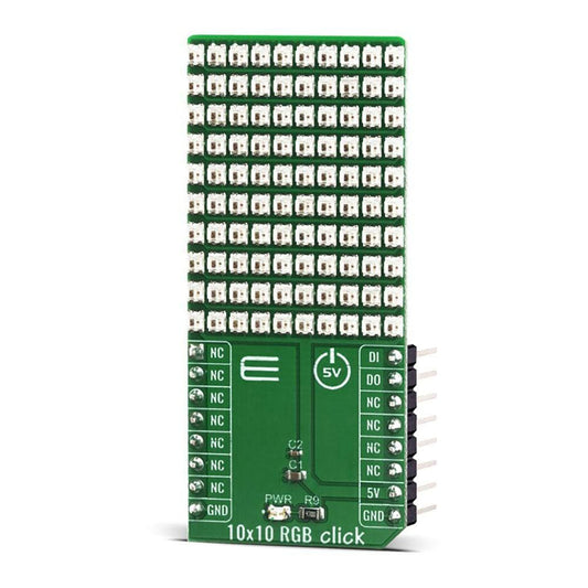
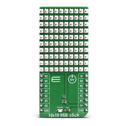
10x10 RGB Click Board™
Vendor:Mikroelektronika d.o.o.Regular price£42.00 inc VAT£35.00 exc VATRegular priceUnit price per£50.00 GBPSale price£42.00 inc VAT£35.00 exc VATSale -
 Sale
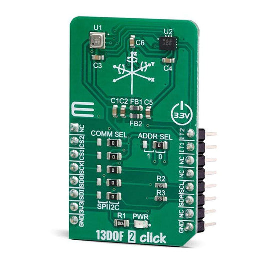
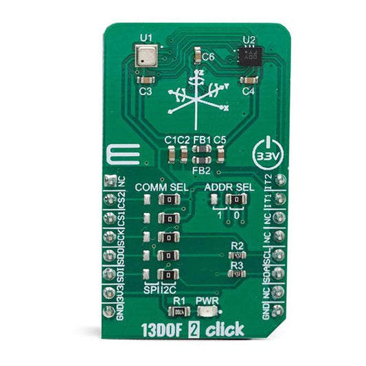
Sale13DOF 2 Click Board™
Vendor:Mikroelektronika d.o.o.Regular price£42.00 inc VAT£35.00 exc VATRegular priceUnit price per£50.00 GBPSale price£42.00 inc VAT£35.00 exc VATSale -
 Sale
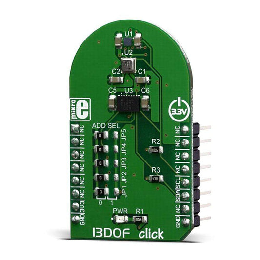
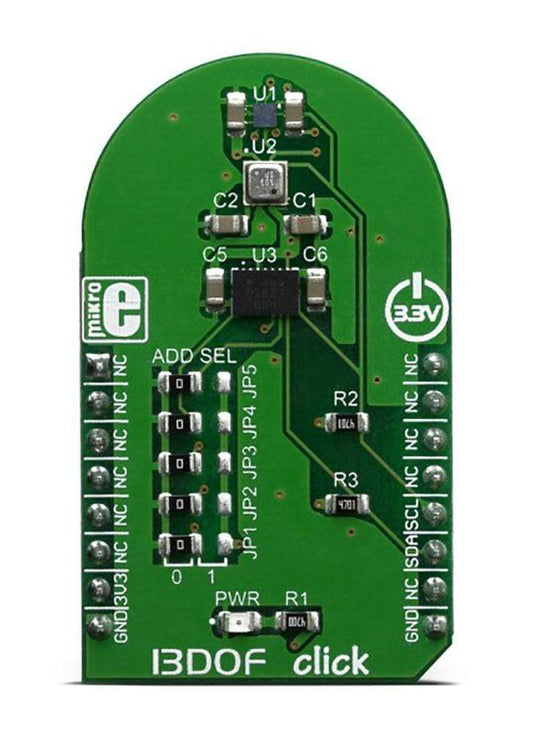
Sale13DOF Click Board™
Vendor:Mikroelektronika d.o.o.Regular price£48.60 inc VAT£40.60 exc VATRegular priceUnit price per£58.00 GBPSale price£48.60 inc VAT£40.60 exc VATSale -
 Sale
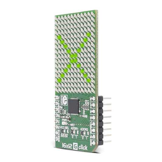
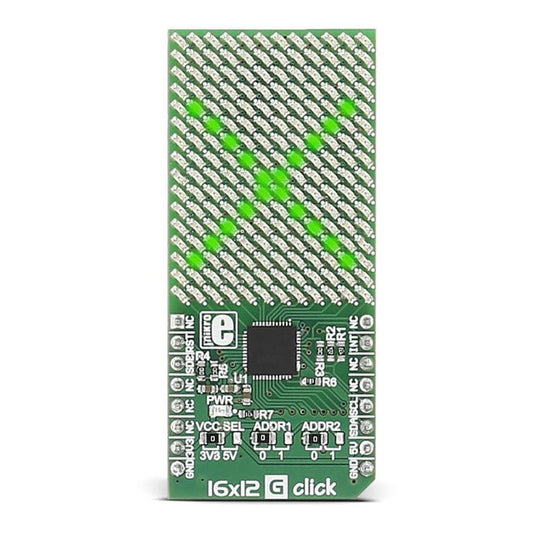
Sale16x12 G Click Board™
Vendor:Mikroelektronika d.o.o.Regular price£30.20 inc VAT£25.20 exc VATRegular priceUnit price per£36.00 GBPSale price£30.20 inc VAT£25.20 exc VATSale -
 Sale
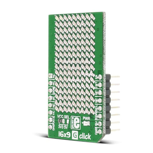
Sale16x9 G Click Board™
Vendor:Mikroelektronika d.o.o.Regular price£34.30 inc VAT£28.70 exc VATRegular priceUnit price per£41.00 GBPSale price£34.30 inc VAT£28.70 exc VATSale -
 Sold out
2 x 30W Amp Click Board™
Vendor:Mikroelektronika d.o.o.Regular price£30.20 inc VAT£25.20 exc VATRegular priceUnit price per£36.00 GBPSale price£30.20 inc VAT£25.20 exc VATSold out -
 Sale
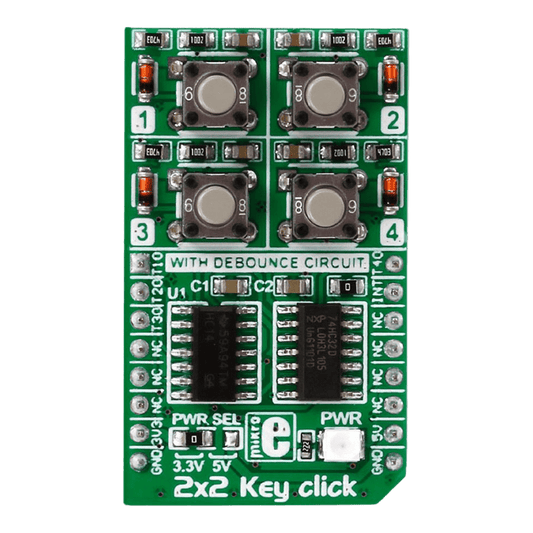
Sale2x2 Key Click Board™
Vendor:Mikroelektronika d.o.o.Regular price£9.10 inc VAT£7.70 exc VATRegular priceUnit price per£11.00 GBPSale price£9.10 inc VAT£7.70 exc VATSale -
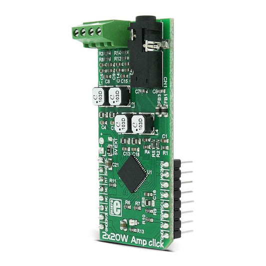
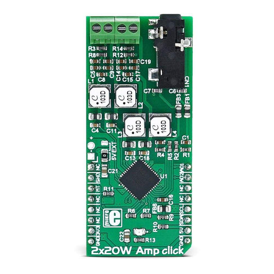
2x20W Amp Click Board™
Vendor:Mikroelektronika d.o.o.Regular price£30.20 inc VAT£25.20 exc VATRegular priceUnit price per£36.00 GBPSale price£30.20 inc VAT£25.20 exc VATSale -
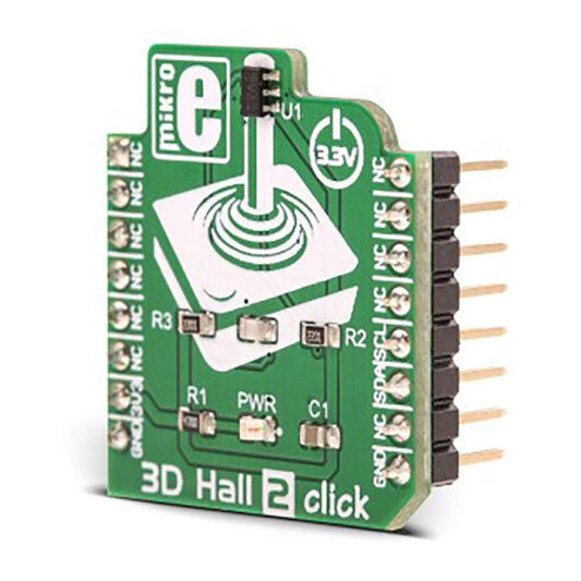
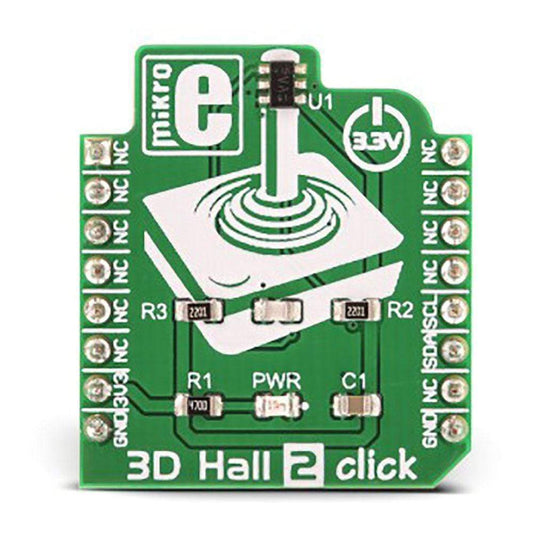
3D Hall 2 Click Board™
Vendor:Mikroelektronika d.o.o.Regular price£15.00 inc VAT£12.60 exc VATRegular priceUnit price per£18.00 GBPSale price£15.00 inc VAT£12.60 exc VATSale -
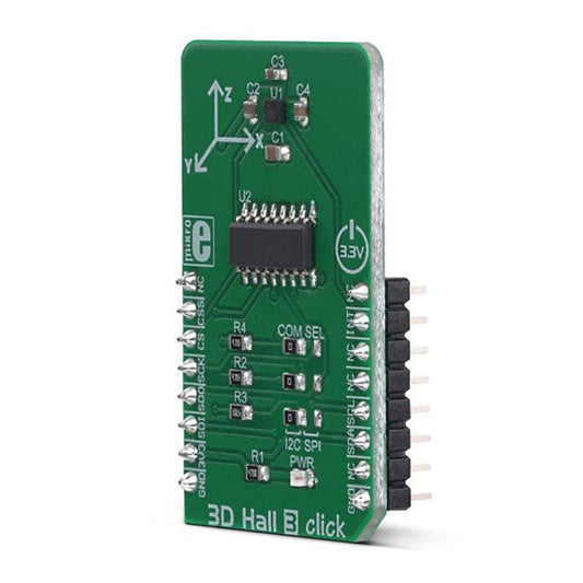
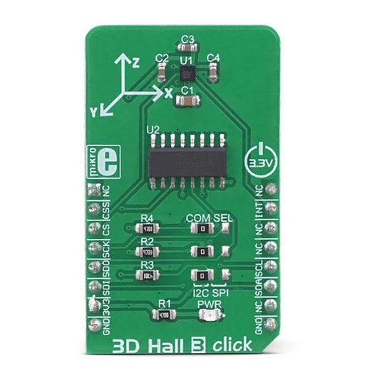
3D Hall 3 Click Board™
Vendor:Mikroelektronika d.o.o.Regular price£15.00 inc VAT£12.60 exc VATRegular priceUnit price per£18.00 GBPSale price£15.00 inc VAT£12.60 exc VATSale -
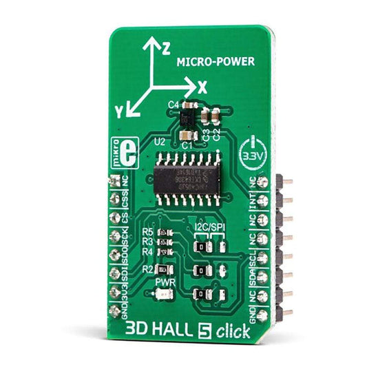
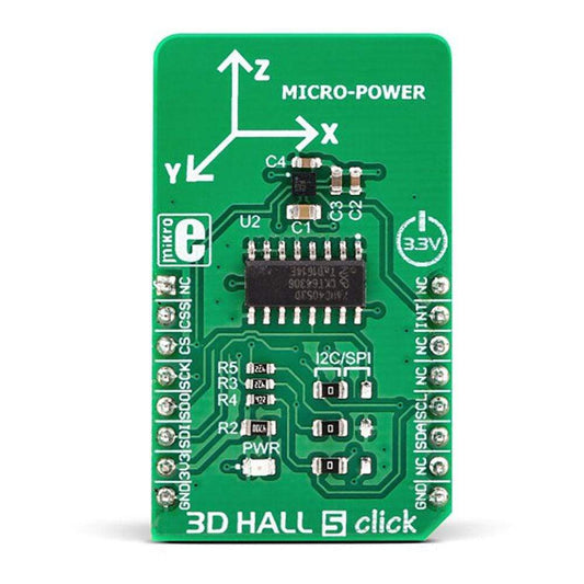
3D Hall 5 Click Board™
Vendor:Mikroelektronika d.o.o.Regular price£15.00 inc VAT£12.60 exc VATRegular priceUnit price per£18.00 GBPSale price£15.00 inc VAT£12.60 exc VATSale -
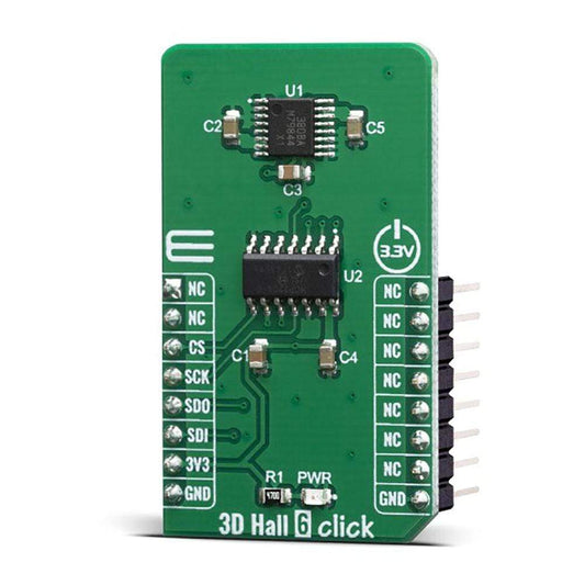
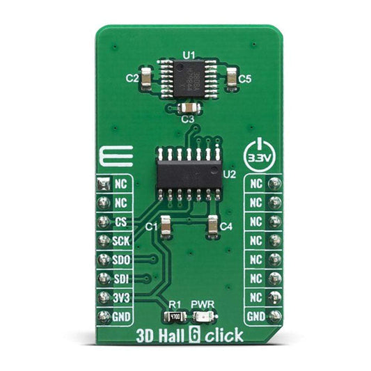
3D Hall 6 Click Board™
Vendor:Mikroelektronika d.o.o.Regular price£34.30 inc VAT£28.70 exc VATRegular priceUnit price per£41.00 GBPSale price£34.30 inc VAT£28.70 exc VATSale -
3D Hall 9 Click Board™
Vendor:Mikroelektronika d.o.o.Regular price£14.10 inc VAT£11.90 exc VATRegular priceUnit price per£17.00 GBPSale price£14.10 inc VAT£11.90 exc VATSale -
 Sale
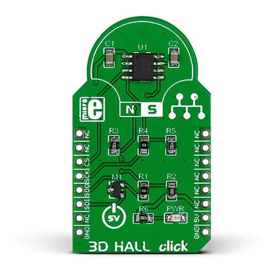
Sale3D Hall Click Board™
Vendor:Mikroelektronika d.o.o.Regular price£25.20 inc VAT£21.00 exc VATRegular priceUnit price per£30.00 GBPSale price£25.20 inc VAT£21.00 exc VATSale -
3D Motion Click Board™
Vendor:Mikroelektronika d.o.o.Regular price£49.50 inc VAT£41.30 exc VATRegular priceUnit price per£59.00 GBPSale price£49.50 inc VAT£41.30 exc VATSale -
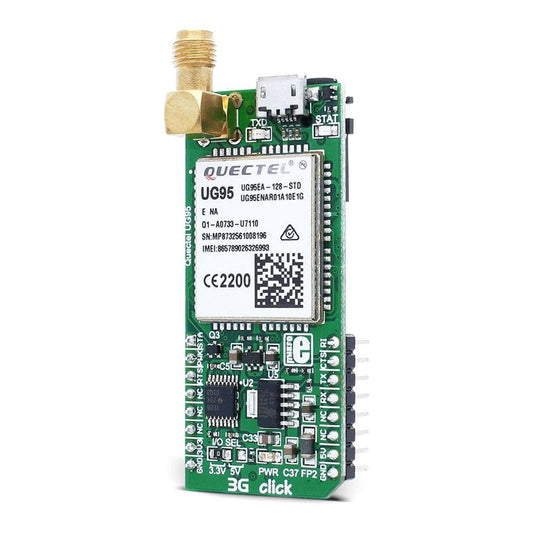
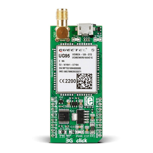
3G-EA Click Board™ (UK, EU and Australia)
Vendor:Mikroelektronika d.o.o.Regular price£83.63 inc VAT£69.83 exc VATRegular priceUnit price per£99.75 GBPSale price£83.63 inc VAT£69.83 exc VATSale