


Mikroelektronika d.o.o.
16x12 G Click Board™
16x12 G Click Board™
SKU: MIKROE-2758
Couldn't load pickup availability


Overview
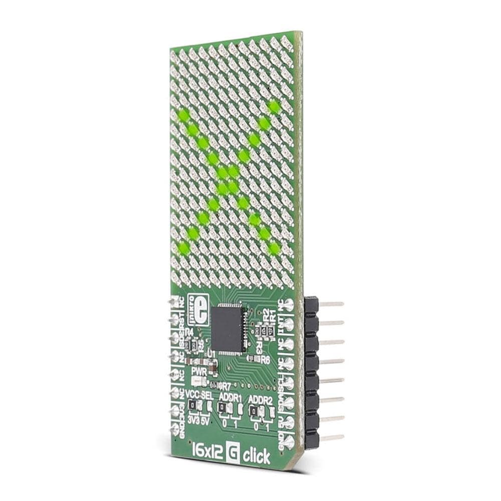
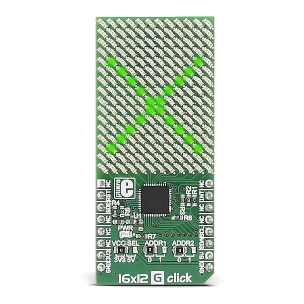
Introducing the 16x12 G Click Board, a versatile and dynamic addition to your electronics projects. This innovative Click Board™ features a 16x12 LED display coupled with the powerful IS31FL3733 matrix driver, offering you a wide range of creative possibilities.
One of the key features of the 16x12 G Click Board is its flexibility in power supply options. Whether you are working with a 3.3V or 5V power source, this Click Board™ is ready to deliver top-notch performance.
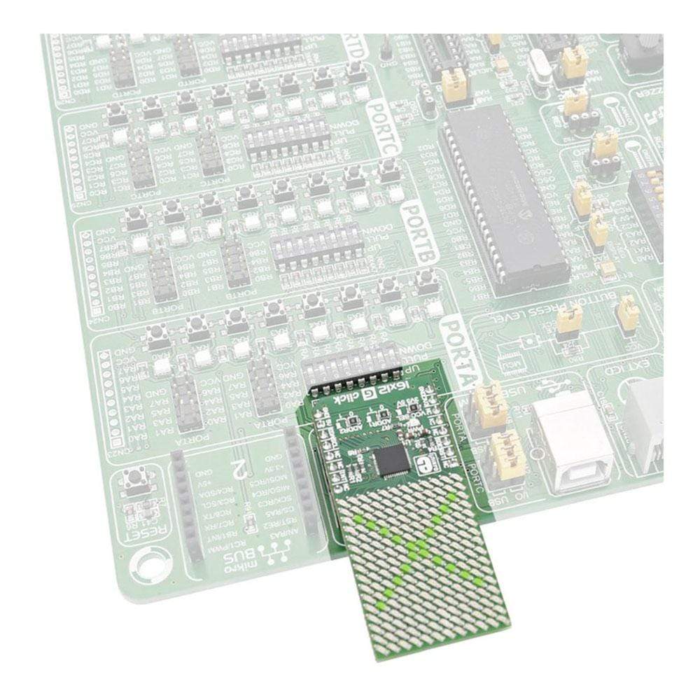
Designed for seamless integration, the 16x12 G Click Board communicates effortlessly with your target microcontroller through the I2C interface and specific pins on the MikroBUS line, including INT, RST, and CS.
Enhance your projects with the vibrant visual capabilities of the 16x12 G Click Board. Whether you are creating eye-catching displays or implementing innovative visual feedback systems, this Click Board™ is sure to impress with its clarity and precision.
Unleash your creativity and bring your ideas to life with the 16x12 G Click Board. Whether you are a seasoned electronics enthusiast or a beginner looking to explore the world of LED displays, this Click Board™ offers a user-friendly experience that is both engaging and rewarding.
Experience the convenience and power of the 16x12 G Click Board today. Elevate your projects with superior visual displays and seamless integration, all in one compact and reliable package.
Downloads
The 16x12 G Click Board™ carries a 16x12 LED display and the IS31FL3733 matrix driver. The click is designed to run on either 3.3V or 5V power supply. It communicates with the target microcontroller over I2C interface, and the following pins on the mikroBUS™ line: INT, RST, CS.
Each LED can be controlled individually – both for on/off control and light intensity.
IS31FL3733 Driver Features
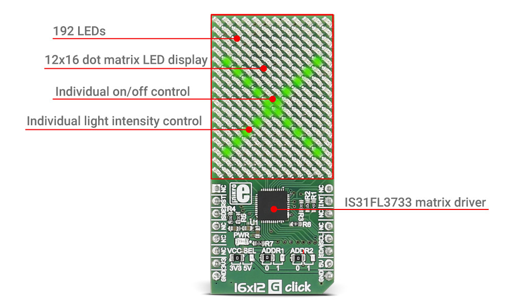
The IS31FL3733 is a general purpose 12×16 LEDs matrix driver with 1/12 cycle rate.
Each of the 192 LEDs can be dimmed individually with 8-bit PWM data, which allows 256 steps of linear dimming.
The driver has selectable 3 Auto Breath Modes for each LED ( ABM-1, ABM-2, and ABM-3).
SPECIFICATIONS
| Type | LED Matrix |
| Applications | The 16x12 G Click Board™ brings serial 8x8 Yellow LED display matrix to your design |
| On-board modules | IS31FL3733 - a general purpose 12×16 LEDs matrix driver with 1/12 cycle rate, from Integrated Silicon Solution, Inc. |
| Key Features | 16 current source outputs for row control, 12 switch current inputs for column scan control, 1MHz I2C-compatible interface |
| Interface | GPIO,I2C |
| Compatibility | mikroBUS |
| Click board size | L (57.15 x 25.4 mm) |
| Input Voltage | 3.3V or 5V |
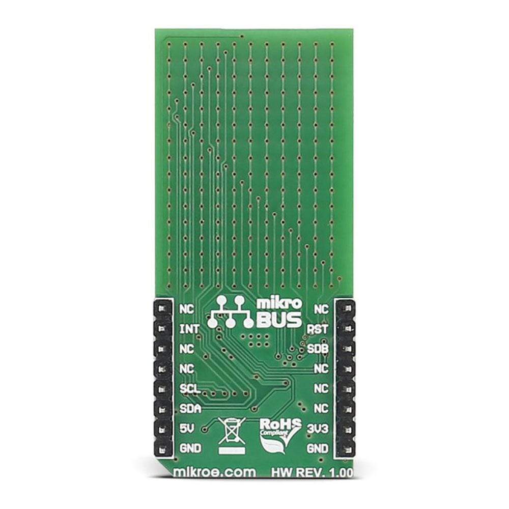
PINOUT DIAGRAM
This table shows how the pinout of the 16x12 G Click Board™ corresponds to the pinout on the mikroBUS™ socket (the latter shown in the two middle columns).
| Notes | Pin | Pin | Notes | ||||
|---|---|---|---|---|---|---|---|
| NC | 1 | AN | PWM | 16 | NC | ||
| Reset | RST | 2 | RST | INT | 15 | INT | Interrupt pin |
| Standby | SDB | 3 | CS | TX | 14 | NC | |
| NC | 4 | SCK | RX | 13 | NC | ||
| NC | 5 | MISO | SCL | 12 | SCL | I2C clock | |
| NC | 6 | MOSI | SDA | 11 | SDA | I2C data | |
| Power supply | +3.3V | 7 | 3.3V | 5V | 10 | +5V | Power supply |
| Ground | GND | 8 | GND | GND | 9 | GND | Ground |
JUMPERS AND SETTINGS
| Designator | Name | Default Position | Default Option | Description |
|---|---|---|---|---|
| JP1 | PWR.SEL. | Left | 3V3 | Power Supply Voltage Selection 3V3/5V, left position 3V3, right position 5V |
| JP2 | ADDR. 1 | Left | 0 | The last two bits of the I2C address |
| JP2 | ADDR. 2 | Left | 0 | The last two bits of the I2C address |
| General Information | |
|---|---|
Part Number (SKU) |
MIKROE-2758
|
Manufacturer |
|
| Physical and Mechanical | |
Weight |
0.022 kg
|
| Other | |
EAN |
8606018711468
|
Frequently Asked Questions
Have a Question?
Be the first to ask a question about this.