


Mikroelektronika d.o.o.
SKU: MIKROE-5524Air Motion Click Board
Air Motion Click Board
Couldn't load pickup availability
Key Features
- Combines a 3-axis gyroscope and accelerometer, integrated TDK’s Air Motion Library, configurable communication interface, user-programmable gyro/accel scale range, programmable interrupts, APEX motion functions, and more
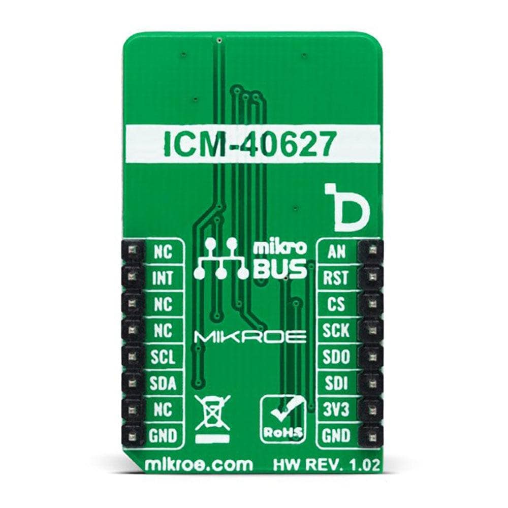
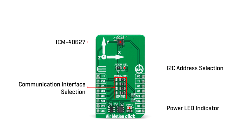
- Based on the ICM-40627 - 6-axis MotionTracking™ device from TDK InvenSense
- Can be used for gesture-based handheld applications, like pedometer, tilt and tap detection, and more
- mikroBUS: I2C and SPI Interfaces
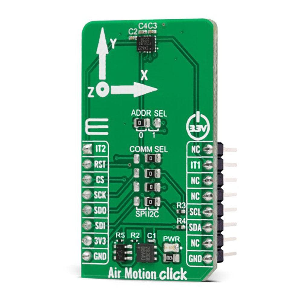
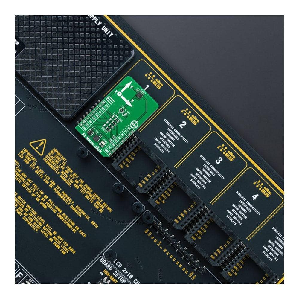
Introduce precision and efficiency to your gesture-based handheld applications with the Air Motion Click Board™. This compact add-on board contains a 6-axis inertial measurement unit featuring the ICM-40627 from TDK InvenSense - a 6-axis MEMS MotionTracking™ device that combines a 3-axis user-selectable gyroscope and accelerometer.
Experience the convenience of the ICM-40627's bundle with TDK's Air Motion Library, enabling precise mouse pointing, swipe, roll and other motion gestures, communicating with the host MCU via a configurable interface (I2C and SPI serial communication). The ICM-40627 also features a 2KB FIFO and two programmable interrupts with ultra-low-power Wake-on-Motion support to minimize system power consumption, making it a perfect fit for pedometer, tilt and tap detection and more.
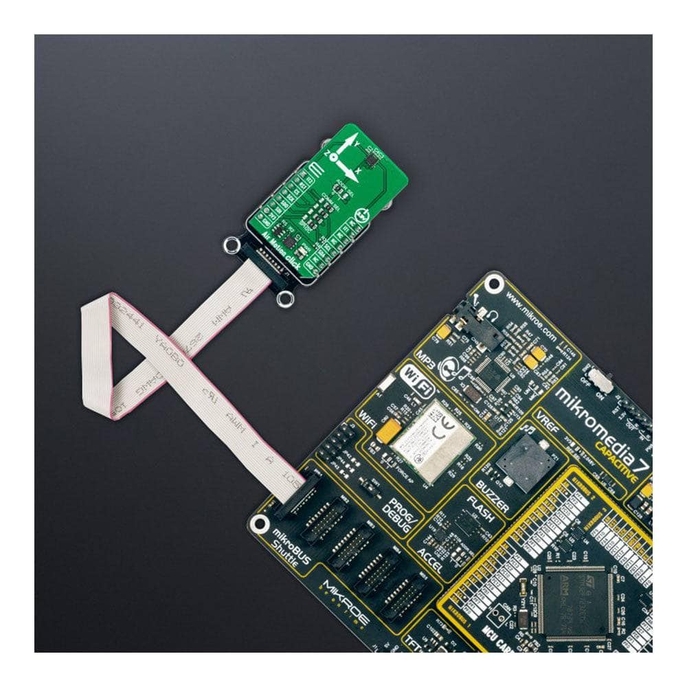
Easily integrate the Air Motion Click Board™ into your system with the mikroSDK-compliant library, which includes functions that simplify software development. And with the added bonus of being a fully tested product, ready to be used on a system equipped with the mikroBUS™ socket, you can trust that the Air Motion Click Board™ will deliver the precise motion tracking results you need. Upgrade your technology today and experience the difference with the Air Motion Click Board™.
How Does The Air Motion Click Board™ Work?
The Air Motion Click Board™ is based on the ICM-40627, a 6-axis MotionTracking™ device that combines a 3-axis gyroscope and a 3-axis accelerometer from TDK InvenSense. It features a 2K-byte FIFO that can lower the traffic on the selected serial bus interface and reduce power consumption by allowing the system processor to burst read sensor data and then go into a low-power mode. With its 6-axis integration, the ICM-40627 guarantees optimal motion performance for customers. The ICM-40627 comes bundled with TDK's Air Motion Library that enables precise mouse pointing, swipe, roll, gesture wake-up and other motion gestures, making this Click board™ a suitable solution for gesture-based handheld applications.
The gyroscope supports eight programmable full-scale range settings from ±15.65dps to ±2000dps, and the accelerometer supports four programmable full-scale range settings from ±2g to ±16g. Other industry-leading features include InvenSense on-chip APEX Motion Processing engine for gesture recognition, activity classification, and pedometer, along with on-chip 16-bit ADCs, programmable digital filters, an embedded temperature sensor, and programmable interrupts.
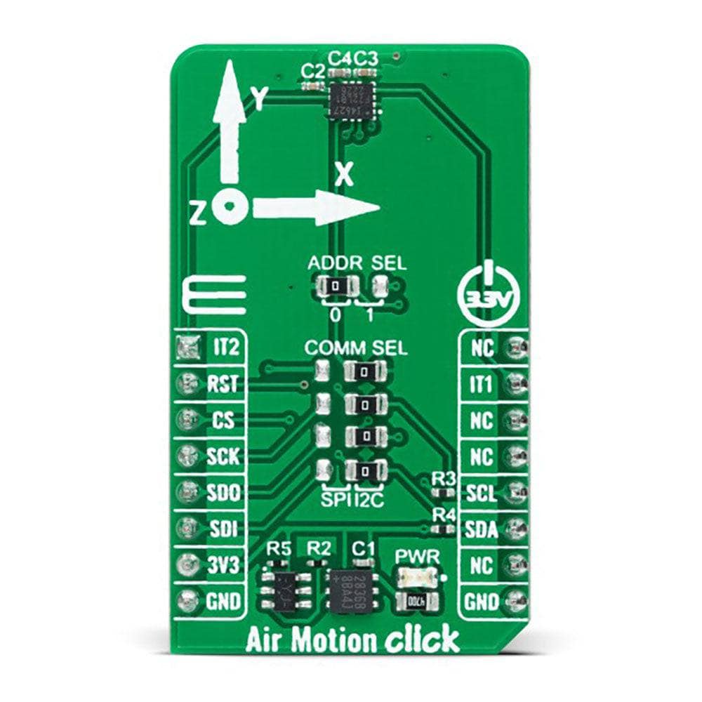
The Air Motion Click Board™ allows using both I2C and SPI interfaces with a maximum frequency of 1MHz for I2C and 24MHz for SPI communication. The selection can be made by positioning SMD jumpers marked as COMM SEL to an appropriate position. Note that all the jumpers' positions must be on the same side, or the Click board™ may become unresponsive. While the I2C interface is selected, the ICM-40627 allows choosing the least significant bit (LSB) of its I2C slave address using the ADDR SEL SMD jumper to an appropriate position marked as 0 and 1.
The ICM-40627 also has a programmable interrupt system, configured via the Interrupt Configuration register, that can generate an interrupt signal on the INT pins, INT1 and INT2 pins routed on the INT and AN pins of the mikroBUS™ socket. Events like new read-data availability (from the FIFO and Data registers), accelerometer events, FIFO watermark and overflow can all trigger an interrupt.
The Air Motion Click Board™ can be operated only with a 3.3V logic voltage level. The board must perform appropriate logic voltage level conversion before using MCUs with different logic levels. However, the Click board™ comes equipped with a library containing functions and an example code that can be used as a reference for further development.
SPECIFICATIONS
| Type | Motion |
| Applications | Can be used for gesture-based handheld applications, like pedometer, tilt and tap detection, and more |
| On-board modules | ICM-40627 - 6-axis MotionTracking™ device from TDK InvenSense |
| Key Features | Combines a 3-axis gyroscope and accelerometer, integrated TDK's Air Motion Library, configurable communication interface, user-programmable gyro/accel scale range, programmable interrupts, APEX motion functions, and more |
| Interface | I2C,SPI |
| Compatibility | mikroBUS |
| Click board size | M (42.9 x 25.4 mm) |
| Input Voltage | 3.3V |
PINOUT DIAGRAM
This table shows how the pinout of the Air Motion Click Board™ corresponds to the pinout on the mikroBUS™ socket (the latter shown in the two middle columns).
| Notes | Pin | Pin | Notes | ||||
|---|---|---|---|---|---|---|---|
| Interrupt 2 | IT2 | 1 | AN | PWM | 16 | NC | |
| NC | 2 | RST | INT | 15 | IT1 | Interrupt 1 | |
| SPI Chip Select | CS | 3 | CS | RX | 14 | NC | |
| SPI Clock | SCK | 4 | SCK | TX | 13 | NC | |
| SPI Data OUT | SDO | 5 | MISO | SCL | 12 | SCL | I2C Clock |
| SPI Data IN | SDI | 6 | MOSI | SDA | 11 | SDA | I2C Data |
| Power Supply | 3.3V | 7 | 3.3V | 5V | 10 | NC | |
| Ground | GND | 8 | GND | GND | 9 | GND | Ground |
ONBOARD SETTINGS AND INDICATORS
| Label | Name | Default | Description |
|---|---|---|---|
| LD1 | PWR | - | Power LED Indicator |
| JP1 | ADDR SEL | Left | I2C Address Selection 0/1: Left position 0, Right position 1 |
| JP2-JP5 | COMM SEL | Right | Communication Interface Selection SPI/I2C: Left position SPI, Right position I2C |
AIR MOTION CLICK ELECTRICAL SPECIFICATIONS
| Description | Min | Typ | Max | Unit |
|---|---|---|---|---|
| Supply Voltage | - | 3.3 | - | V |
| Gyroscope Range | ±2000 | - | ±15.625 | dps |
| Accelerometer Range | ±2 | - | ±16 | g |
| Gyroscope Sensitivity | 16.4 | - | 2097.2 | LBS/dps |
| Accelerometer Sensitivity | 2.048 | - | 16.384 | LBS/g |
| Resolution | - | 16 | - | bits |
Software Support
We provide a library for the Air Motion Click Board™ as well as a demo application (example), developed using MikroE compilers. The demo can run on all the main MikroE development boards.
The package can be downloaded/installed directly from NECTO Studio The package Manager(recommended), downloaded from our LibStock™ or found on MikroE Github account.
Library Description
This library contains API for the Air Motion Click Board™ driver.
Key functions
-
airmotion_set_reg_bankAir Motion set register bank function. -
airmotion_sw_resetAir Motion software reset function. -
airmotion_get_data_from_registerAir Motion read data function.
Example Description
This example demonstrates the use of the Air Motion Click Board™.\
void application_task ( void )
 {
 if ( airmotion_get_int1_state( &airmotion) )
 {
 #if defined TAP_DETECTION_MODE
 uint8_t tap_num;
 uint8_t tap_axis;
 uint8_t tap_dir;
 airmotion_get_tap_detection( &airmotion, &tap_num, &tap_axis, &tap_dir );
 if ( AIRMOTION_TAP_SINGLE == tap_num )
 {
 log_printf( &logger, " SINGLE TAP" );
 }
 else
 {
 log_printf( &logger, " DOUBLE TAP" );
 }
 if ( AIRMOTION_TAP_DIR_POSITIVE == tap_dir )
 {
 log_printf( &logger, " IN POSITIVE" );
void application_task ( void )
 {
     if ( airmotion_get_int1_state( &airmotion) )
     {
 #if defined TAP_DETECTION_MODE
         uint8_t tap_num;
         uint8_t tap_axis;
         uint8_t tap_dir;

         airmotion_get_tap_detection( &airmotion, &tap_num, &tap_axis, &tap_dir );
         if (  AIRMOTION_TAP_SINGLE == tap_num )
         {
             log_printf( &logger, " SINGLE TAP" );
         }
         else
         {
             log_printf( &logger, " DOUBLE TAP" );
         }

         if (  AIRMOTION_TAP_DIR_POSITIVE == tap_dir )
         {
             log_printf( &logger, " IN POSITIVE" );
         }
         else
         {
             log_printf( &logger, " IN NEGATIVE" );
         }

         if (  AIRMOTION_TAP_AXIS_X == tap_axis )
         {
             log_printf( &logger, " X AXIS DIRECTION rn" );
         }
         else if ( AIRMOTION_TAP_AXIS_Y == tap_axis )
         {
             log_printf( &logger, " Y AXIS DIRECTION  rn" );
         }
         else
         {
             log_printf( &logger, " Z AXIS DIRECTION  rn" );
         }
 #else
         airmotion_data_t accel_data;
         airmotion_data_t gyro_data;
         float temp_data;
         uint32_t tmst_data;

         airmotion_get_data_from_register( &airmotion, &temp_data, &accel_data, &gyro_data, &tmst_data );
         log_printf( &logger, " TEMP: %.2f rn", temp_data );
         log_printf( &logger, " GYRO: x:%d y:%d z:%d rn", gyro_data.data_x,gyro_data.data_y,gyro_data.data_z );
         log_printf( &logger, " ACCEL: x:%d y:%d z:%d rn", accel_data.data_x,accel_data.data_y,accel_data.data_z );
         log_printf( &logger, "========================== rn" );
         Delay_ms(1000);
 #endif
     }
 }
The full application code, and ready to use projects can be installed directly from NECTO Studio The package Manager(recommended), downloaded from our LibStock™ or found on MikroE Github account.
Other MikroE Libraries used in the example:
- MikroSDK.Board
- MikroSDK.Log
- Click.AirMotion
Additional Notes and Information
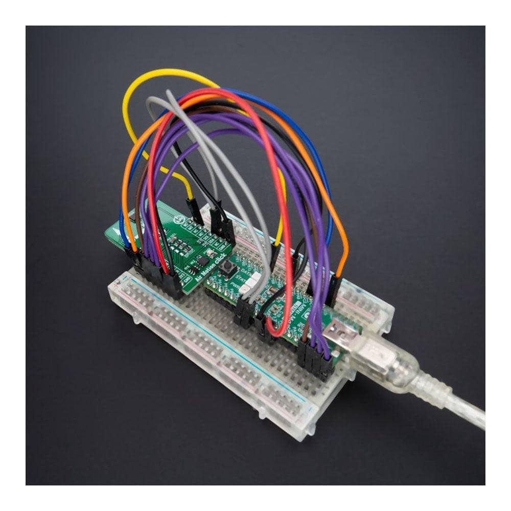
Depending on the development board you are using, you may need USB UART Click Board™, USB UART 2 Click or RS232 Click to connect to your PC, for development systems with no UART to USB interface available on the board. UART terminal is available in all MikroE compilers.
MIKROSDK
The Air Motion Click Board™ is supported with mikroSDK - MikroE Software Development Kit. To ensure proper operation of mikroSDK compliant Click board™ demo applications, mikroSDK should be downloaded from the LibStock and installed for the compiler you are using.
Air Motion Click Board
Frequently Asked Questions
Have a Question?
Be the first to ask a question about this.