


Mikroelektronika d.o.o.
SKU: MIKROE-5475ADAC 2 Click Board
ADAC 2 Click Board
Couldn't load pickup availability
Key Features
- High accuracy, flexibility, software-configurable for voltage and current mode, high resolution, RTD and thermocouple measurements, SPI interface, additional GPIOs, protection features, and more
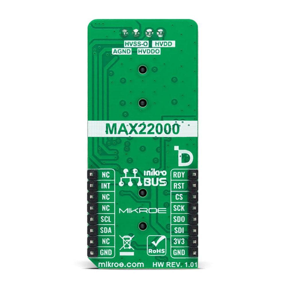
- Based on the MAX22000 - industrial-grade, software-configurable analogue input/output solution from Analog Devices
- Can be used for industrial applications such as programmable logic controllers (PLCs), programmable automation controllers (PACs), and process control applications
- mikroBUS: SPI Interface
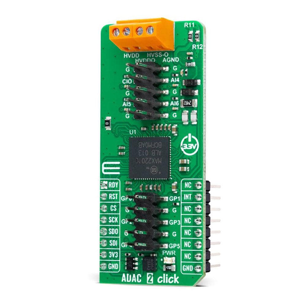
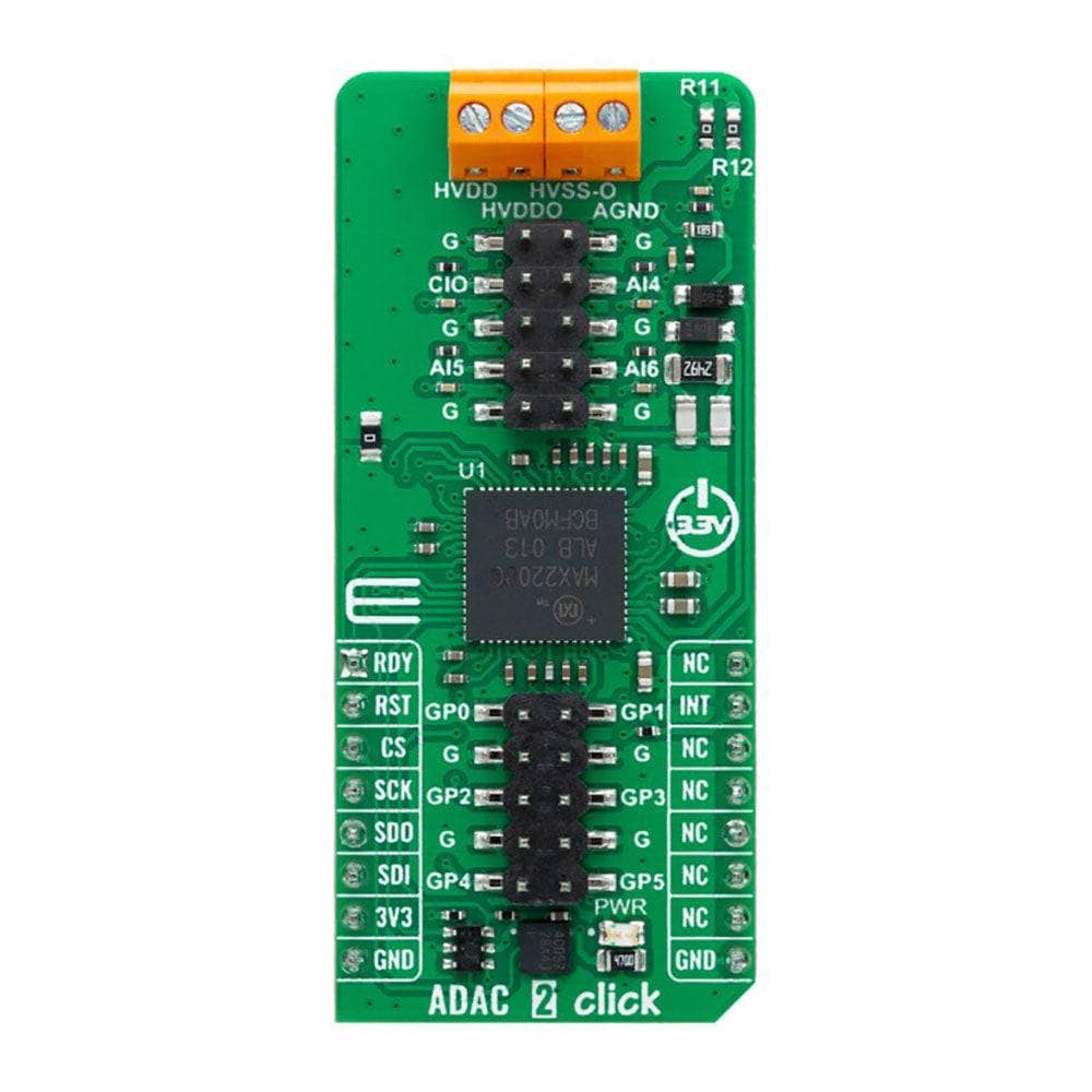
The ADAC 2 Click Board™ is a compact add-on board providing the ADC/DAC combo solution. This board features the MAX22000, a 24-bit ADC, an 18-bit DAC, and an analogue front-end (AFE) from Analog Devices. It allows users to create a software-configurable (SPI interface) input/output that supports all standard industrial analogue interfaces: -10V to +10V analogue input or output, -20mA to +20mA analogue input or output, as well as an RTD or thermocouple input for temperature measurement. This Click board™ is designed to support industrial applications such as programmable logic controllers (PLCs), programmable automation controllers (PACs), and process control applications that require configurable analogue I/O.
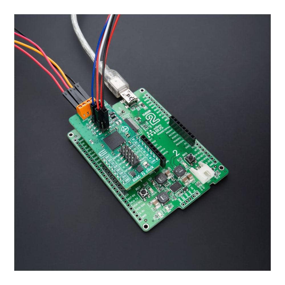
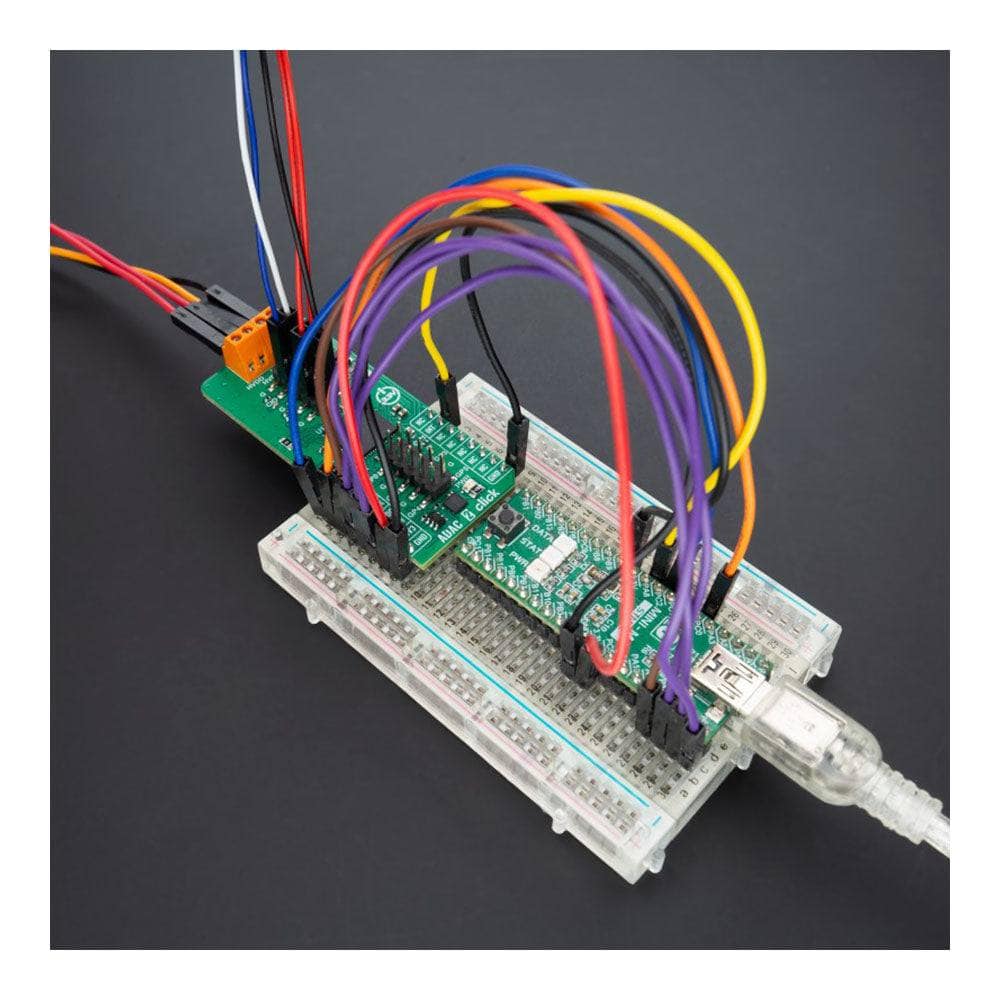
The ADAC 2 Click Board™ is supported by a mikroSDK-compliant library, which includes functions that simplify software development. This Click board™ comes as a thoroughly tested product, ready to be used on a system equipped with the mikroBUS™ socket.


How Does The ADAC 2 Click Board™ Work?
The ADAC 2 Click Board™ is based on the MAX22000, an industrial-grade, software-configurable analogue input/output solution from Analog Devices. It provides a high-performance 18-bit DAC in the transmit path and a 24-bit delta-sigma ADC in the receive path. The transmit path (analogue output), and the receive path (analogue inputs) are entirely independent; thus, they can be programmed for different configurations and modes of operation. Thanks to its outstanding performance and features, this board is designed to support various industrial applications such as programmable logic controllers (PLCs), programmable automation controllers (PACs), and process control applications that require configurable analogue I/O.
The ADAC 2 Click Board™ communicates with MCU through a standard SPI interface for all configuration and management information with a maximum frequency of 20MHz. The MAX22000 provides multiple voltages and current ranges for its inputs and outputs to maintain the best accuracy. It sets the linear range at 105% of the nominal range and the full scale at 125% of the nominal range. For example, for a ±10V nominal range, the MAX22000 provides a linear range of ±10.5V and a full-scale range of ±12.5V. Achieving other ranges can be done by configuring the appropriate registers.
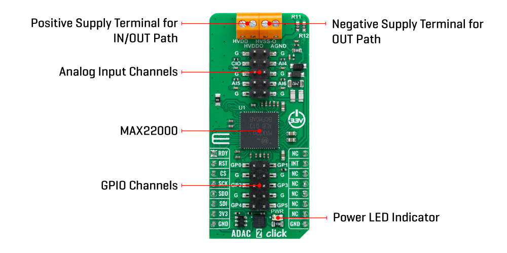
The MAX22000 also offers one output marked as CIO, configured as voltage or current output, alongside three analogue inputs (AI4, AI5, and AI6) configurable as voltage or current inputs. Besides their use as general-purpose analogue inputs, the AI5 and AI6 pins can also be configured as differential programmable gain amplifiers (PGA) for either low-voltage or high-voltage inputs to support RTD and thermocouple measurements. A high-performance filter follows the ADC to provide 50Hz/60Hz normal mode rejection at selected ADC data rates.
Current measurement using AI5 and AI6 pins relies on an external precision resistor to perform the current-to-voltage conversion. A GPIO pin on the additional GPIO header can control an external analogue switch to connect or disconnect the current sense resistor electronically for current measurements that do not use a differential sensor.
In addition, it also uses several mikroBUS™ pins. An active-low reset signal routed on the RST pin of the mikroBUS™ socket activates a hardware reset of the system (all registers go to their power-on default states, analogue output goes high impedance, analogue inputs power down, and ADC conversion stops). In contrast, the INT pin on the mikroBUS™ socket represents a standard interrupt feature providing a user with feedback information. It also has an additional data-ready interrupt marked as RDY and routed on the AN pin of the mikroBUS™ socket, used to signal when a new ADC conversion result is available in the data register.
The ADAC 2 Click Board™ can be operated only with a 3.3V logic voltage level. The board must perform appropriate logic voltage level conversion before using MCUs with different logic levels. However, the Click board™ comes equipped with a library containing functions and an example code that can be used as a reference for further development.
SPECIFICATIONS
| Type | ADC-DAC |
| Applications | It can be used for industrial applications such as programmable logic controllers (PLCs), programmable automation controllers (PACs), and process control applications |
| On-board modules | MAX22000 - industrial-grade, software-configurable analog input/output solution from Analog Devices |
| Key Features | High accuracy, flexibility, software-configurable for voltage and current mode, high resolution, RTD and thermocouple measurements, SPI interface, additional GPIOs, protection features, and more |
| Interface | SPI |
| Compatibility | mikroBUS |
| Click board size | L (57.15 x 25.4 mm) |
| Input Voltage | 3.3V |
PINOUT DIAGRAM
This table shows how the pinout of the ADAC 2 Click Board™ corresponds to the pinout on the mikroBUS™ socket (the latter shown in the two middle columns).
| Notes | Pin | Pin | Notes | ||||
|---|---|---|---|---|---|---|---|
| Data Ready | RDY | 1 | AN | PWM | 16 | NC | |
| Reset | RST | 2 | RST | INT | 15 | INT | Interrupt |
| SPI Chip Select | CS | 3 | CS | RX | 14 | NC | |
| SPI Clock | SCK | 4 | SCK | TX | 13 | NC | |
| SPI Data OUT | SDO | 5 | MISO | SCL | 12 | NC | |
| SPI Data IN | SDI | 6 | MOSI | SDA | 11 | NC | |
| Power Supply | 3.3V | 7 | 3.3V | 5V | 10 | NC | |
| Ground | GND | 8 | GND | GND | 9 | GND | Ground |
ONBOARD SETTINGS AND INDICATORS
| Label | Name | Default | Description |
|---|---|---|---|
| LD1 | PWR | - | Power LED Indicator |
| J1 | - | Populated | Analog Input Connection Header |
| J2 | - | Populated | GPIO Connection Header |
ADAC 2 CLICK ELECTRICAL SPECIFICATIONS
| Description | Min | Typ | Max | Unit |
|---|---|---|---|---|
| Supply Voltage | - | 3.3 | - | V |
| Operating Voltage Range | ±5 | - | ±24 | V |
| Input Resolution | - | 24 | - | bits |
| Output Resolution | - | 18 | - | bits |
| Output Voltage Range | - | ±12.5 | - | V |
| Output Current Range | - | ±25 | - | mA |
Software Support
We provide a library for the ADAC 2 Click and a demo application (example), developed using MikroE compilers. The demo can run on all the main MikroE development boards.
The package can be downloaded/installed directly from NECTO Studio The package Manager(recommended), downloaded from our LibStock™ or found on the MikroE Github account.
Library Description
This library contains API for ADAC 2 Click driver.
Key functions
-
adac2_set_active_ain_channelThis function sets the active analogue input channel. -
adac2_read_voltageThis function reads RAW ADC value of the previous conversion and converts it to voltage. -
adac2_write_dacThis function sets the analogue output by writing to the AO_DATA_WR register.
Example Description
This example demonstrates the use of the ADAC 2 Click Board™ by setting the DAC output (CIO) and reading the ADC results from a single-ended channel (AI4) and from a differential channel (AI5+, AI6-) as well as toggling all GPIO pins.
void application_task ( void )
 {
     float voltage;
     if ( ADAC2_OK == adac2_set_active_ain_channel ( &adac2, ADAC2_CH_AI4_SINGLE_ENDED ) )
     {
         adac2_start_conversion ( &adac2, ADAC2_DATA_RATE_450_SPS );
         // Waits for the availability of the conversion result
         while ( adac2_get_rdy_pin ( &adac2 ) );
         adac2_stop_conversion ( &adac2 );
         if ( ADAC2_OK == adac2_read_voltage ( &adac2, ADAC2_FULL_SCALE_RANGE_12p5V, &voltage ) )
         {
             log_printf ( &logger, " Channel AI4 single-ended: %.2f Vrn", voltage );
         }
     }
     if ( ADAC2_OK == adac2_set_active_ain_channel ( &adac2, ADAC2_CH_AI5_AI6_DIFFERENTIAL_25V ) )
     {
         adac2_start_conversion ( &adac2, ADAC2_DATA_RATE_450_SPS );
         // Waits for the availability of the conversion result
         while ( adac2_get_rdy_pin ( &adac2 ) );
         adac2_stop_conversion ( &adac2 );
         if ( ADAC2_OK == adac2_read_voltage ( &adac2, ADAC2_FULL_SCALE_RANGE_25V, &voltage ) )
         {
             log_printf ( &logger, " Channel AI5-AI6 differential: %.2f Vrn", voltage );
         }
     }

     static int32_t dac = ADAC2_DAC_MIN_VALUE;
     if ( ADAC2_OK == adac2_write_dac ( &adac2, dac ) )
     {
         log_printf ( &logger, " DAC: %ldrn", dac );
         dac += 5000;
         if ( dac > ADAC2_DAC_MAX_VALUE )
         {
             dac = ADAC2_DAC_MIN_VALUE;
         }
     }

     uint32_t gpio_data;
     if ( ADAC2_OK == adac2_read_register ( &adac2, ADAC2_REG_GEN_GPIO_CTRL, &gpio_data ) )
     {
         gpio_data ^= ADAC2_GPIO_ALL_MASK;
         if ( ADAC2_OK == adac2_write_register ( &adac2, ADAC2_REG_GEN_GPIO_CTRL, gpio_data ) )
         {
             log_printf ( &logger, " GPIO: 0x%.2Xrnn", ( uint16_t ) ( gpio_data & ADAC2_GPIO_ALL_MASK ) );
         }
     }
     Delay_ms ( 1000 );
 }
The complete application code and ready-to-use projects can be installed directly from NECTO Studio, The package Manager(recommended), downloaded from our LibStock™ or found on the MikroE Github account.
Other MikroE Libraries used in the example:
- MikroSDK.Board
- MikroSDK.Log
- Click.ADAC2
Additional Notes and Information
Depending on the development board you are using, you may need USB UART Click Board™, USB UART 2 Click or RS232 Click to connect to your PC, for development systems with no UART to USB interface available on the board. UART terminal is available in all MikroE compilers.
MIKROSDK
The ADAC 2 Click Board™ is supported with mikroSDK - MikroE Software Development Kit. To ensure proper operation of mikroSDK compliant Click board™ demo applications, mikroSDK should be downloaded from the LibStock and installed for the compiler you are using.
ADAC 2 Click Board
Frequently Asked Questions
Have a Question?
Be the first to ask a question about this.