


Mikroelektronika d.o.o.
SKU: MIKROE-5468Boost 8 Click Board
Boost 8 Click Board
Couldn't load pickup availability
Key Features
- Regulated negative and positive outputs, current-limited, high efficiency, fixed off-time control scheme, low power consumption, selectable converter power supply, software-controlled output channels, and more
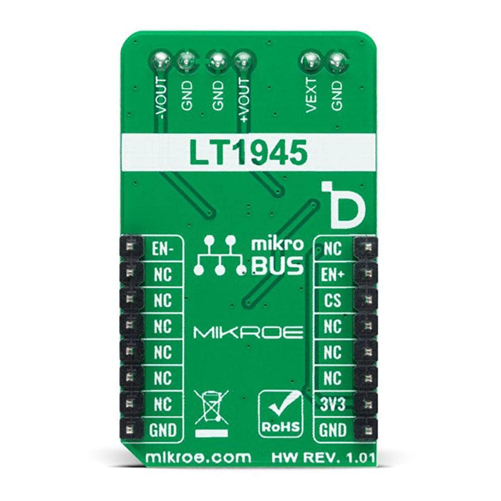
- Based on the LT1945 - dual micropower DC/DC converter from Analog Devices
- Can be used to step up an input voltage to some higher level
- mikroBUS: GPIO Interface
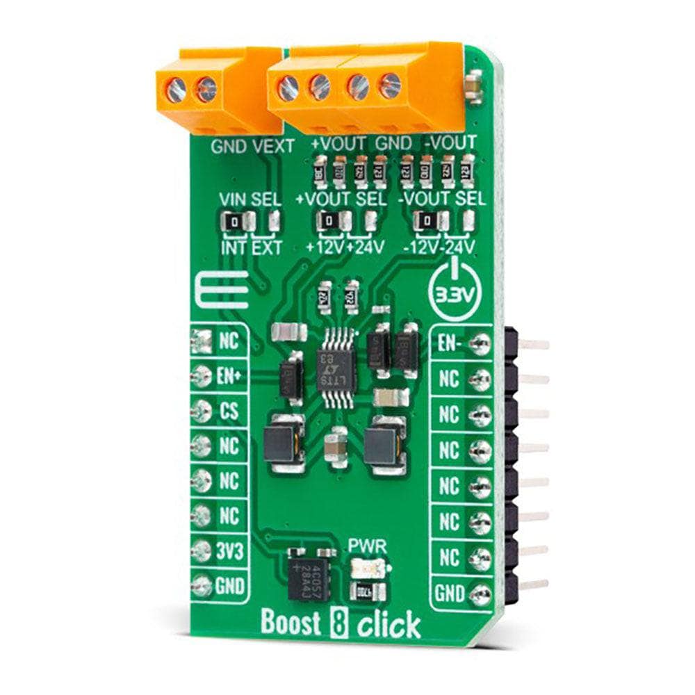
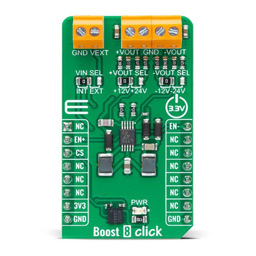
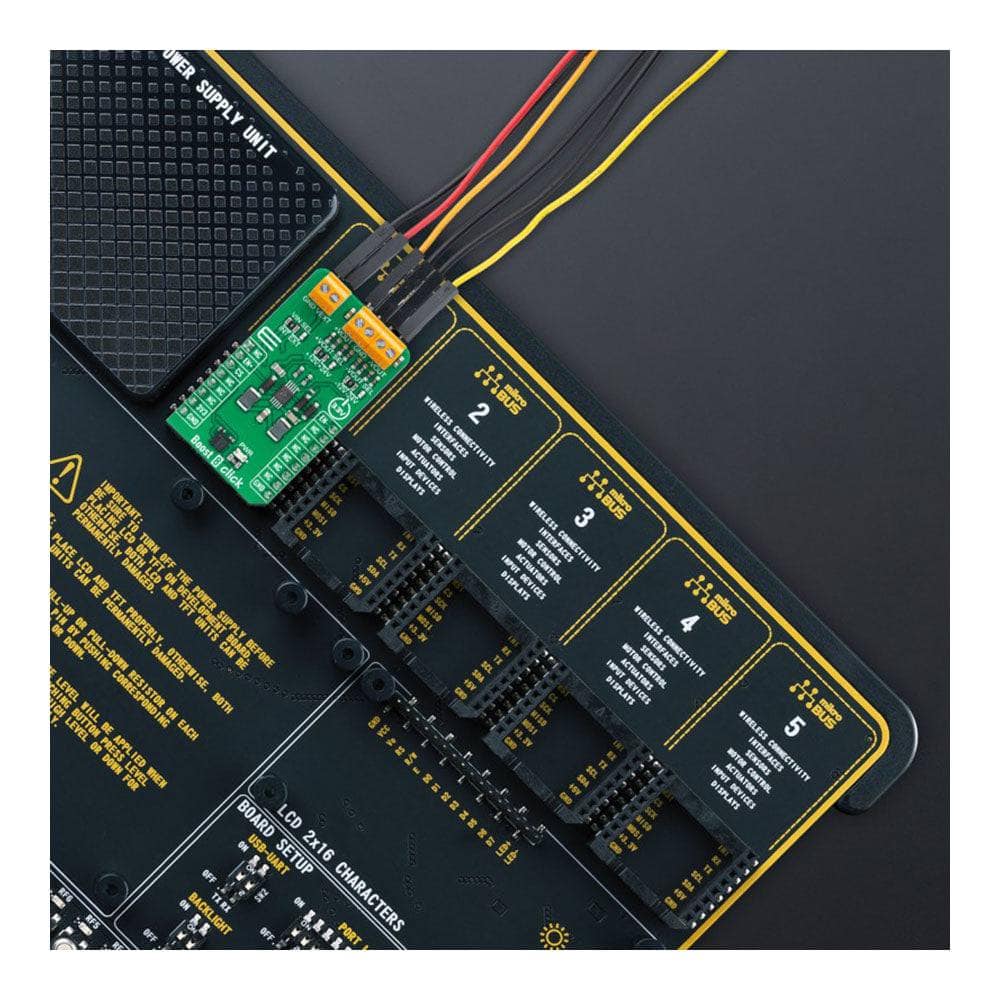
The Boost 8 Click Board™ is a compact add-on board that steps-up the voltage from its input (supply) to its output (load). This board features the LT1945, a dual micropower DC/DC converter from Analog Devices. Each converter inside the LT1945 is designed with a 350mA current limit generating well-regulated positive and negative outputs of ±12V or ±24V, making the LT1945 ideal for various applications. In addition to the possibility of working with a 3.3V mikroBUS™ power rail, it also provides the opportunity of using an external power supply with a very low voltage of 2.7V. A current-limited, fixed-off-time control scheme conserves operating current, resulting in high efficiency over a broad range of load current. This Click board™ is used to step up an input voltage to some higher level, required by a load, for various applications that require "split rail" operating voltages.
The Boost 8 Click Board™ is supported by a mikroSDK-compliant library, which includes functions that simplify software development. This Click board™ comes as a thoroughly tested product, ready to be used on a system equipped with the mikroBUS™ socket.
How Does The Boost 8 Click Board™ Work?
The Boost 8 Click Board™ is based on the LT1945, a dual micropower DC/DC converter from Analog Devices that boosts an input voltage to a higher level required by an output load. The LT1945 uses a constant off-time control scheme to provide high efficiency over a wide range of output currents. Each converter inside the LT1945 is designed with a 350mA current limit generating well-regulated positive and negative outputs of ±12V or ±24V, making the LT1945 ideal for various applications. It also contains additional circuitry to provide protection during the Start-Up sequence and under short-circuit conditions, reducing the average inductor output current and minimizing the power dissipation in the power switch.
As mentioned before, the LT1945 can configure the positive and negative output voltage in the ±12V or ±24V range. The desired output voltage can be selected by positioning SMD jumpers labelled as +VOUT SEL and -VOUT SEL to an appropriate position. It is also possible to control the activity of the output channels via two mikroBUS™ pins, EN+ and EN- pins, routed to the RST and PWM pin of the mikroBUS™ socket. By setting these pins to a high logic state, we set the converter outputs to an active state, and regulated voltages are available at the output terminals. In the same way, setting these pins to a low logic level disables the channels.
The Boost 8 Click Board™ can be operated only with a 3.3V logic voltage level. The board must perform appropriate logic voltage level conversion before using MCUs with different logic levels. Additionally, there is a possibility for the LT1945 power supply selection via jumper labelled as VIN SEL to supply the LT1945 from an external power supply terminal in the range from 2.7V to 5V or with 3.3V from mikroBUS™ power rail. However, the Click board™ comes equipped with a library containing easy-to-use functions and an example code that can be used, as a reference, for further development.
SPECIFICATIONS
| Type | Boost |
| Applications | Can be used to step up an input voltage to some higher level |
| On-board modules | LT1945 - dual micropower DC/DC converter from Analog Devices |
| Key Features | Regulated negative and positive outputs, current-limited, high efficiency, fixed off-time control scheme, low power consumption, selectable converter power supply, software-controlled output channels, and more |
| Interface | GPIO |
| Compatibility | mikroBUS |
| Click board size | M (42.9 x 25.4 mm) |
| Input Voltage | 3.3V,External |
PINOUT DIAGRAM
This table shows how the pinout of Boost 8 Click Board™ corresponds to the pinout on the mikroBUS™ socket (the latter shown in the two middle columns).
| Notes | Pin | Pin | Notes | ||||
|---|---|---|---|---|---|---|---|
| NC | 1 | AN | PWM | 16 | EN- | Negative Channel Control | |
| Positive Channel Control | EN + | 2 | RST | INT | 15 | NC | |
| NC | 3 | CS | RX | 14 | NC | ||
| NC | 4 | SCK | TX | 13 | NC | ||
| NC | 5 | MISO | SCL | 12 | NC | ||
| NC | 6 | MOSI | SDA | 11 | NC | ||
| Power Supply | 3.3V | 7 | 3.3V | 5V | 10 | NC | |
| Ground | GND | 8 | GND | GND | 9 | GND | Ground |
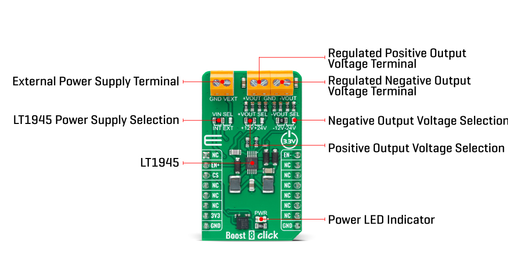
ONBOARD SETTINGS AND INDICATORS
| Label | Name | Default | Description |
|---|---|---|---|
| LD1 | PWR | - | Power LED Indicator |
| JP1 | +VOUT SEL | Left | Positive Output Voltage Selection +12V/+24V: Left position +12V, Right position +24V |
| JP2 | -VOUT SEL | Left | Negative Output Voltage Selection -12V/-24V: Left position -12V, Right position -24V |
| JP3 | VIN SEL | Left | LT1945 Power Supply Selection INT/EXT: Left position INT, Right position EXT |
BOOST 8 CLICK ELECTRICAL SPECIFICATIONS
| Description | Min | Typ | Max | Unit |
|---|---|---|---|---|
| Supply Voltage | - | 3.3 | - | V |
| External Supply Voltage | 2.7 | - | 5 | V |
| Positive Output Voltage | - | 12/24 | - | V |
| Negative Output Voltage | - | -12/-24 | - | V |
Software Support
We provide a library for the Boost 8 Click Board™ as well as a demo application (example), developed using MikroE compilers. The demo can run on all the main MikroE development boards.
The package can be downloaded/installed directly from NECTO Studio The package Manager(recommended), downloaded from our LibStock™ or found on MikroE Github account.
Library Description
This library contains API for the Boost 8 Click Board™ driver.
Key functions
-
boost8_enable_positive_voltageEnable positive voltage output function. -
boost8_disable_positive_voltageDisable positive voltage output function. -
boost8_enable_negative_voltageEnable negative voltage output function.
Example Description
This is an example that demonstrates the use of the Boost 8 Click Board™.
void application_task ( void )
 {
     char inx;

     // Waiting for the user input and performing actions based on a selected command.
     if ( log_read( &logger, &inx, 1 ) != BOOST8_ERROR )
     {
         switch(inx)
         {
             case '1' :
             {
                 log_printf( &logger, "Turning on positive output rn" );
                 boost8_enable_positive_voltage( &boost8 );
                 break;
             }
             case '2' :
             {
                 log_printf( &logger, "Turning off positive output rn" );
                 boost8_disable_positive_voltage( &boost8 );
                 break;
             }
             case '3' :
             {
                 log_printf( &logger, "Turning on negative output rn" );
                 boost8_enable_negative_voltage( &boost8 );
                 break;
             }
             case '4':
             {
                 log_printf( &logger, "Turning off negative output rn" );
                 boost8_disable_negative_voltage( &boost8 );
                 break;
             }
             case '5' :
             {
                 log_printf( &logger, "Turning on both outputs rn" );
                 boost8_enable_both_outputs( &boost8 );
                 break;
             }
             case '6' :
             {
                 log_printf( &logger, "Turning off both outputs rn" );
                 boost8_disable_both_outputs( &boost8 );
                 break;
             }
             default:
             {
                 log_printf( &logger, "> Invalid command rn" );
                 boost8_list_of_commands();
                 break;
             }
         }
     }

 }
The full application code, and ready to use projects can be installed directly from NECTO Studio The package Manager(recommended), downloaded from our LibStock™ or found on MikroE Github account.
Other MikroE Libraries used in the example:
- MikroSDK.Board
- MikroSDK.Log
- Click.Boost8
Additional Notes and Information
Depending on the development board you are using, you may need USB UART Click Board™, USB UART 2 Click or RS232 Click to connect to your PC, for development systems with no UART to USB interface available on the board. UART terminal is available in all MikroE compilers.
MIKROSDK
The Boost 8 Click Board™ is supported with mikroSDK - MikroE Software Development Kit. To ensure proper operation of mikroSDK compliant Click board™ demo applications, mikroSDK should be downloaded from the LibStock and installed for the compiler you are using.
Boost 8 Click Board
Frequently Asked Questions
Have a Question?
Be the first to ask a question about this.