


Mikroelektronika d.o.o.
SKU: MIKROE-5447LR IoT Click Board
LR IoT Click Board
Couldn't load pickup availability
Key Features
- Low power consumption, worldwide ISM bands support, high efficiency and sensitivity, multi-purpose radio front-end targeting geolocation purposes, SPI interface, interrupt and reset, and more
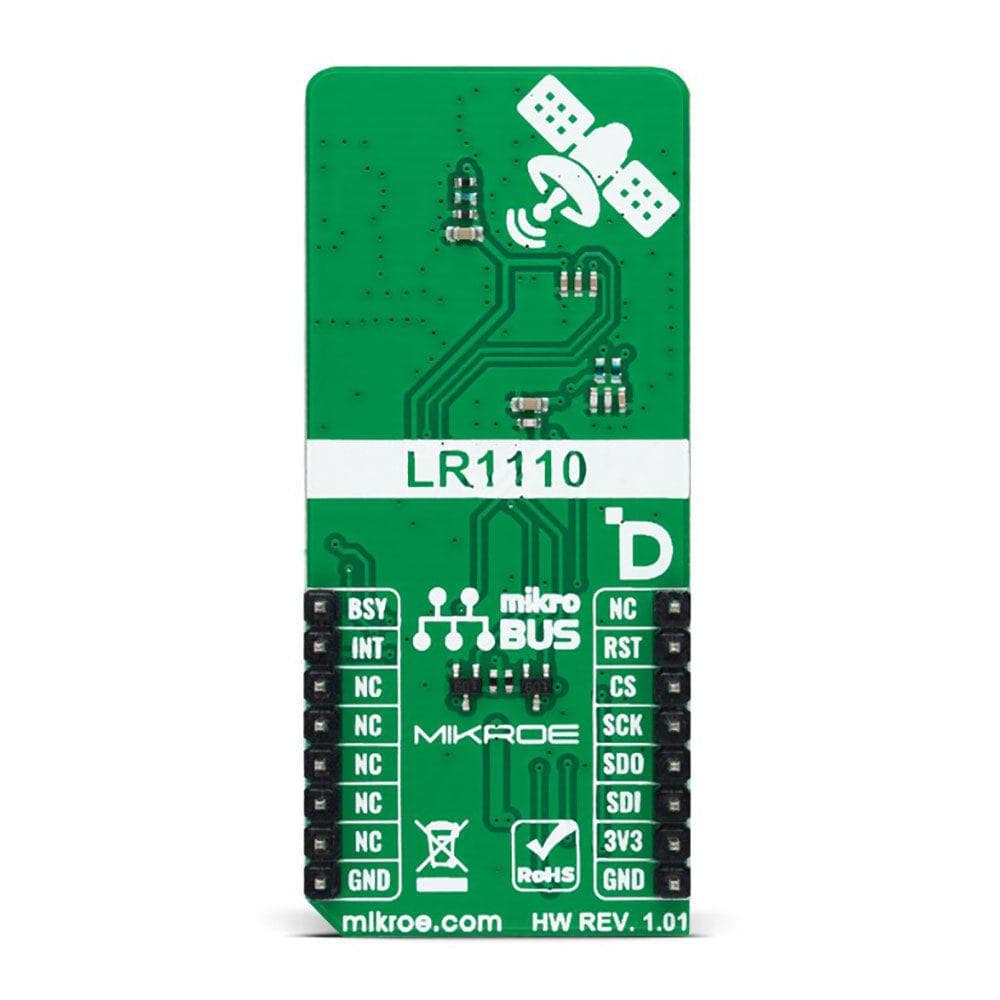
- Based on the LR1110 - long-range, ultra-low power transceiver from the Semtech Corporation
- Can be used for asset location, traceability, loss and theft prevention, asset recovery, and inventory management
- mikroBUS: SPI Interface
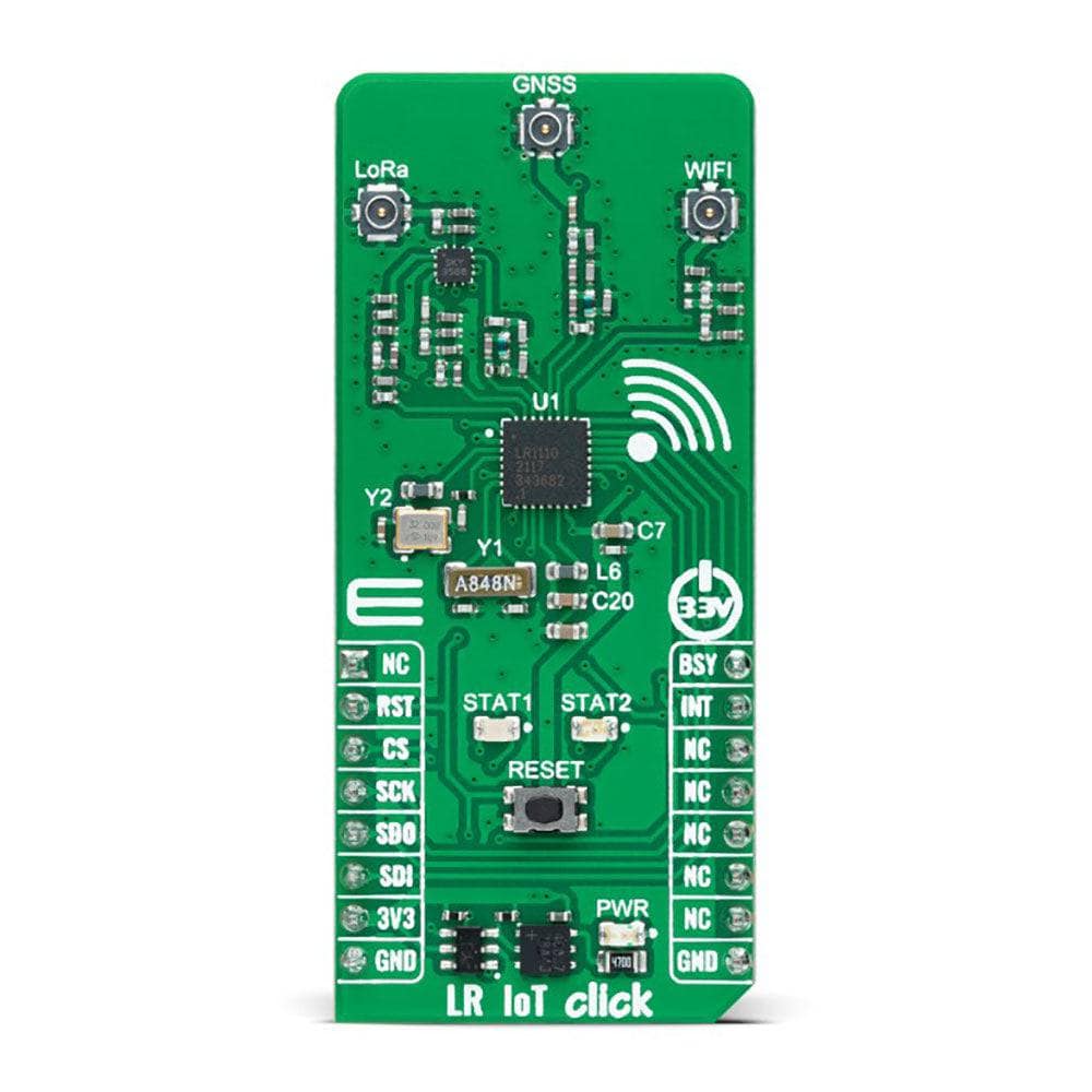
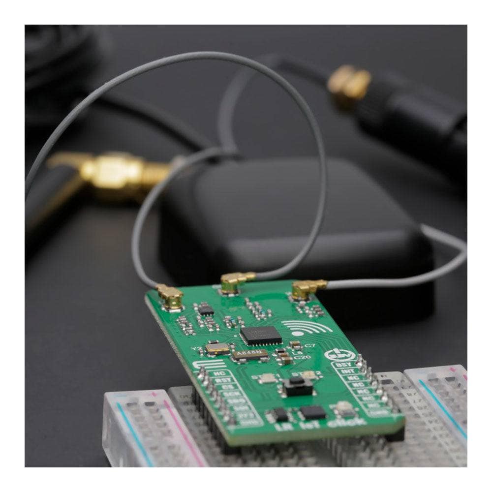
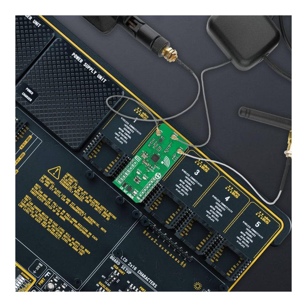
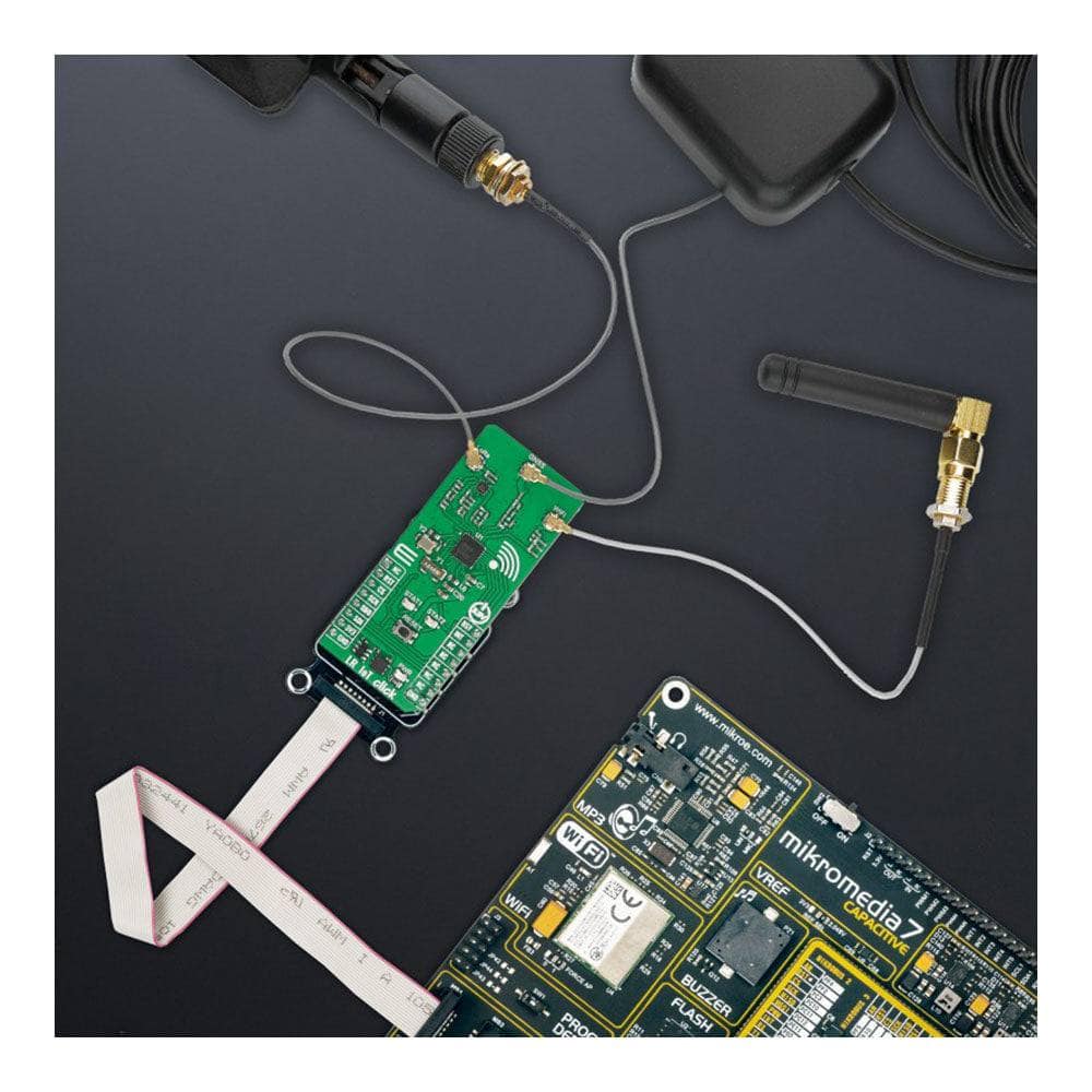
The LR IoT Click Board™ is a compact add-on board that contains a long-range transceiver. This board features Semtech Corporation’s LR1110, an ultra-low power platform integrating a LoRa® transceiver, multi-constellation GNSS, and passive WiFi AP MAC address scanner. Alongside its sub-GHz capabilities, the LR1110 also has a multi-band front-end capable of receiving 802.11b/g/n WiFi Access Point MAC addresses and GNSS (GPS, BeiDou, geostationary) satellite raw data befitting geo-positioning purposes. The acquired information is then transmitted using an LPWAN network to a geolocation server, which analyzes it and correlates the position with data from a geolocation database, enabling a unique balance between low power and performance. This Click board™ is highly configurable to meet different application requirements utilizing the global LoRaWAN® standard or proprietary protocols, targeting geolocation applications.
The LR IoT Click Board™ is supported by a mikroSDK-compliant library, which includes functions that simplify software development. This Click board™ comes as a thoroughly tested product, ready to be used on a system equipped with the mikroBUS™ socket.

How Does The LR IoT Click Board™ Work?
The LR IoT Click Board™ is based on the LR1110, a long-range, ultra-low power transceiver from Semtech Corporation aimed to enhance LoRa®-based geolocation applications. This platform solution is highly configurable over the 150-960MHz ISM bands and supports LoRa® and (G)FSK modulations for LPWAN use cases. Besides, the LR1110 also features a low-power multi-band front-end that can acquire several signals of opportunity for geolocation purposes (802.11b/g/n WiFi AP MAC addresses, GNSS (GPS, BeiDou) satellites signals) and then transmit them using LPWAN network to a geolocation server, which computes the position of the object. This Click board™ is optimized for low-power applications requiring indoor and outdoor geolocation, such as asset location, traceability, loss and theft prevention, asset recovery, and inventory management.
The LR1110 uses three operating modes: WiFi passive scanning and two GNSS modes for outdoor geolocation, such as GNSS autonomous and assisted modes. With WiFi passive scanning, the LR1110 can discover the WiFi b/g/n access points available in the vicinity of the device and extract MAC addresses to geolocate them. The objective is to obtain at least 2 MAC addresses and position the device after being sent to an online WiFi lookup service. The WiFi passive scanning implemented in LR1110 can also extract the country code information of an access point contained in the beacon or probe response.
In addition to WiFi, there is also a fast and low-power GNSS scanner, which captures a short portion of the signal broadcast by the GNSS satellites, and extracts the information required to calculate the device position. This information is then aggregated into a NAV message which can be sent to a back-end system to compute the device position. As mentioned before, the GNSS scanner has two modes of operation: autonomous and assisted. In autonomous mode, which does not require any assistance data, the LR1110 searches and decodes the signal from the strong satellites for indoor/outdoor detection, while in the assisted mode, allows searching for all the visible satellites and also requires connectivity with the geolocation server for calculation of the device position.
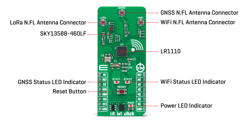
The LR IoT Click Board™ communicates with MCU through a standard SPI interface supporting the most common SPI mode, SPI Mode 0, with a maximum frequency of 16MHz. It also possesses an interrupt pin, routed to the INT pin of the mikroBUS™ socket, allowing the host MCU to react to special events in the LR1110 system without register-poll. A "BUSY" indicator, labelled as BSY and routed to the PWM pin of the mikroBUS™ socket, indicating that the internal MCU can't receive any commands from the host MCU, and general reset function routed on the RST pin of the mikroBUS™ socket as well as on the onboard RESET button. Besides, it uses two LED indicators labelled STAT1 and STAT2 for optional GNSS and WiFi network-activity status visual indications. Still, they can also be configured according to the wishes and needs of the user himself.
The LR IoT Click Board™ can be operated only with a 3.3V logic voltage level. The board must perform appropriate logic voltage level conversion before using MCUs with different logic levels. However, the Click board™ comes equipped with a library containing functions and an example code that can be used as a reference for further development.
SPECIFICATIONS
| Type | LoRa |
| Applications | It can be used for asset location, traceability, loss and theft prevention, asset recovery, and inventory management |
| On-board modules | LR1110 - long-range, ultra-low power transceiver from Semtech Corporation |
| Key Features | Low power consumption, worldwide ISM bands support, high efficiency and sensitivity, multi-purpose radio front-end targeting geolocation purposes, SPI interface, interrupt and reset, and more |
| Interface | SPI |
| Compatibility | mikroBUS |
| Click board size | L (57.15 x 25.4 mm) |
| Input Voltage | 3.3V |
PINOUT DIAGRAM
This table shows how the pinout of the LR IoT Click Board™ corresponds to the pinout on the mikroBUS™ socket (the latter shown in the two middle columns).
| Notes | Pin | Pin | Notes | ||||
|---|---|---|---|---|---|---|---|
| NC | 1 | AN | PWM | 16 | BSY | Busy Indicator | |
| Reset | RST | 2 | RST | INT | 15 | INT | Interrupt |
| SPI Chip Select | CS | 3 | CS | RX | 14 | NC | |
| SPI Clock | SCK | 4 | SCK | TX | 13 | NC | |
| SPI Data OUT | SDO | 5 | MISO | SCL | 12 | NC | |
| SPI Data IN | SDI | 6 | MOSI | SDA | 11 | NC | |
| Power Supply | 3.3V | 7 | 3.3V | 5V | 10 | NC | |
| Ground | GND | 8 | GND | GND | 9 | GND | Ground |
ONBOARD SETTINGS AND INDICATORS
| Label | Name | Default | Description |
|---|---|---|---|
| LD1 | PWR | - | Power LED Indicator |
| LD2 | STAT2 | - | WiFi Status LED Indicator |
| LD3 | STAT1 | - | GNSS Status LED Indicator |
| T1 | Reset | - | Reset Button |
LR IOT CLICK ELECTRICAL SPECIFICATIONS
| Description | Min | Typ | Max | Unit |
|---|---|---|---|---|
| Supply Voltage | - | 3.3 | - | V |
| Operating Frequency Range | 150 | - | 960 | MHz |
Software Support
We provide a library for the LR IoT Click Board™ as well as a demo application (example), developed using MikroE compilers. The demo can run on all the main MikroE development boards.
The package can be downloaded/installed directly from NECTO Studio The package Manager(recommended), downloaded from our LibStock™ or found on MikroE Github account.
Library Description
This library contains API for the LR IoT Click Board™ driver.
Key functions
-
lriot_get_wifi_scan_resultsThis function performs a WiFi scanning and reads the results. -
lriot_get_gnss_scan_resultsThis function performs a GNSS scanning and reads the results. -
lriot_send_lora_messageThis function sends a LoRa message to the receiver.
Example Description
This example demonstrates the use of the LR IoT Click Board™ board by reading a GNSS and WiFi scanning results and displaying it on the USB UART. In the case of a tranceive firmware the communication between two devices over LoRa will be demonstrated as well.
 void application_task ( void )
 {
 #if ( LRIOT_FIRMWARE_SELECTOR == LRIOT_TRANSCEIVE_FIRMWARE )
     uint8_t lora_buffer[ LRIOT_LORA_PKT_PAYLOAD_LEN ] = { 0 };
     #ifdef DEMO_APP_TRANSMITTER
         lriot_gnss_scan_results_t gnss_results = { 0 };
         lriot_wifi_scan_results_t wifi_results = { 0 };
         uint8_t tmp_buf[ 30 ] = { 0 };
         float temperature = 0;

         if ( LRIOT_OK == lriot_get_gnss_scan_results ( &lriot, &gnss_results ) )
         {
             lriot_display_gnss_scan_results ( gnss_results );
         }

         memset( lora_buffer, 0, sizeof ( lora_buffer ) );
         strcpy( lora_buffer, "Number of sattelites found is " );
         uint16_to_str ( gnss_results.num_satellites, tmp_buf );
         l_trim ( tmp_buf );
         strcat( lora_buffer, tmp_buf );
         if ( LRIOT_OK == lriot_send_lora_message ( &lriot, lora_buffer ) )
         {
             log_printf( &logger, "Send LoRa message - donern" );
         }

         if ( LRIOT_OK == lriot_get_wifi_scan_results ( &lriot, &wifi_results ) )
         {
             lriot_display_wifi_scan_results ( wifi_results );
         }
         memset( lora_buffer, 0, sizeof ( lora_buffer ) );
         strcpy( lora_buffer, "Number of WiFi scan results is " );
         uint16_to_str ( wifi_results.num_wifi_results, tmp_buf );
         l_trim ( tmp_buf );
         strcat( lora_buffer, tmp_buf );
         if ( LRIOT_OK == lriot_send_lora_message ( &lriot, lora_buffer ) )
         {
             log_printf( &logger, "Send LoRa message - donern" );
         }

         log_printf ( &logger, "**************************************************************rn" );
         if ( LRIOT_OK == lriot_get_temperature ( &lriot, &temperature ) )
         {
             log_printf ( &logger, "Temperature : %.2f degCrn", temperature );
         }
         memset( lora_buffer, 0, sizeof ( lora_buffer ) );
         strcpy( lora_buffer, "My temperature is " );
         float_to_str ( temperature, tmp_buf );
         l_trim ( tmp_buf );
         tmp_buf[ 5 ] = 0;
         strcat( lora_buffer, tmp_buf );
         strcat( lora_buffer, " degC" );
         if ( LRIOT_OK == lriot_send_lora_message ( &lriot, lora_buffer ) )
         {
             log_printf( &logger, "Send LoRa message - donern" );
         }
     #else
         lriot_lora_packet_status_t pkt_status;
         if ( LRIOT_OK == lriot_read_lora_message ( &lriot, &pkt_status, lora_buffer ) )
         {
             log_printf ( &logger, "**************************************************************rn" );
             log_printf ( &logger, "*                      RECEIVED LORA PACKET                  *rn" );
             log_printf ( &logger, "**************************************************************rn" );
             log_printf ( &logger, " RSSI        : %d dBmrn", ( uint16_t ) pkt_status.rssi_pkt_in_dbm );
             log_printf ( &logger, " Signal RSSI : %d dBmrn", ( uint16_t ) pkt_status.signal_rssi_pkt_in_dbm );
             log_printf ( &logger, " SNR         : %d dBrn", ( uint16_t ) pkt_status.snr_pkt_in_db );
             log_printf ( &logger, " Message     : "%s"rnn", lora_buffer );
         }
     #endif
 #else
     lriot_gnss_scan_results_t gnss_results = { 0 };
     lriot_wifi_scan_results_t wifi_results = { 0 };

     if ( LRIOT_OK == lriot_get_gnss_scan_results ( &lriot, &gnss_results ) )
     {
         lriot_display_gnss_scan_results ( gnss_results );
     }

     if ( LRIOT_OK == lriot_get_wifi_scan_results ( &lriot, &wifi_results ) )
     {
         lriot_display_wifi_scan_results ( wifi_results );
     }
 #endif
 }
The full application code, and ready to use projects can be installed directly from NECTO Studio The package Manager(recommended), downloaded from our LibStock™ or found on MikroE Github account.
Other MikroE Libraries used in the example:
- MikroSDK.Board
- MikroSDK.Log
- Click.LRIoT
Additional Notes and Information
Depending on the development board you are using, you may need USB UART Click Board™, USB UART 2 Click or RS232 Click to connect to your PC, for development systems with no UART to USB interface available on the board. UART terminal is available in all MikroE compilers.
MIKROSDK
The LR IoT Click Board™ is supported with mikroSDK - MikroE Software Development Kit. To ensure proper operation of mikroSDK compliant Click board™ demo applications, mikroSDK should be downloaded from the LibStock and installed for the compiler you are using.
LR IoT Click Board
Frequently Asked Questions
Have a Question?
Be the first to ask a question about this.