


Mikroelektronika d.o.o.
SKU: MIKROE-5302XBee 2 Click Board
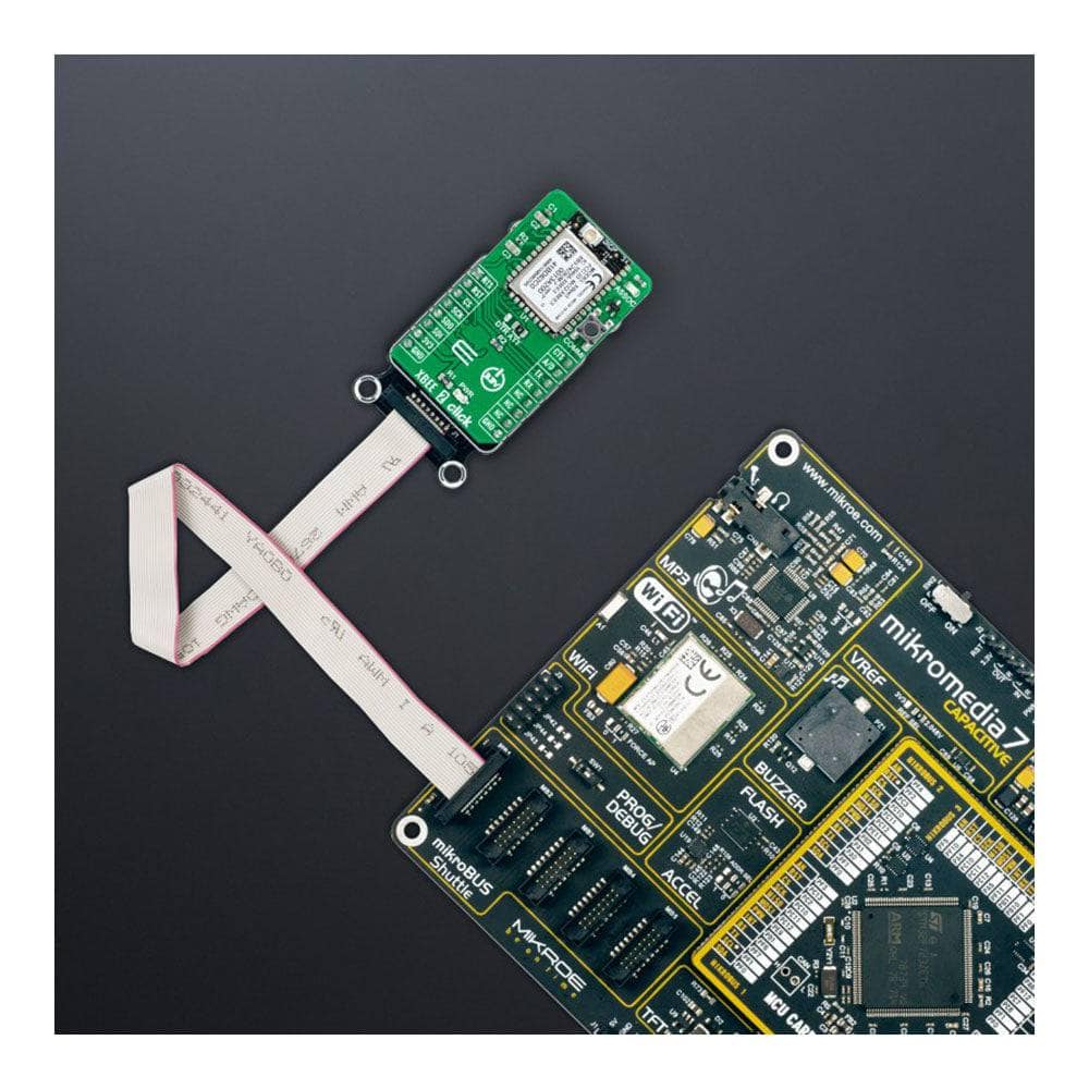
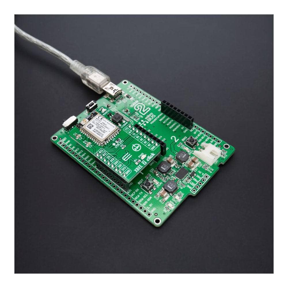
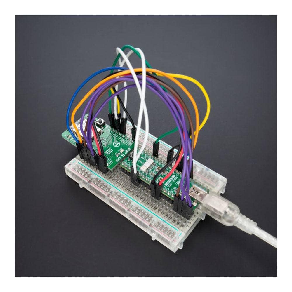
XBee 2 Click Board
Couldn't load pickup availability
Key Features
- Industry-leading technology, pre-certified, flexibility, multiple frequencies and wireless protocols, security features, high programmability, and more
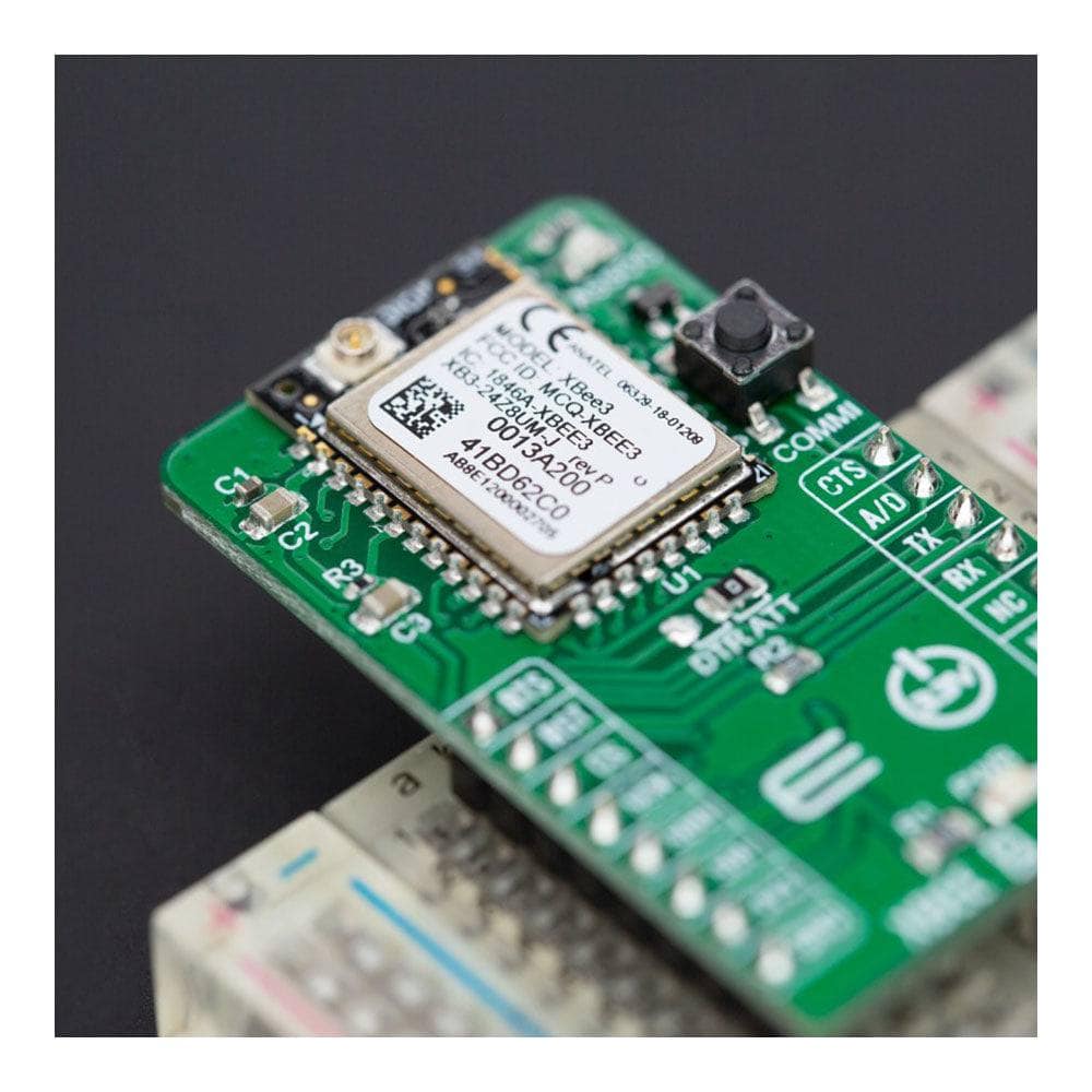
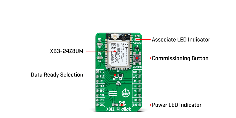
- Based on the XB3-24Z8UM - Digi XBee® 3 Zigbee 3.0 radio module providing wireless end-point connectivity from Digi International
- Can be used for broad smart-energy applications, wireless alarms and security, building automation, and others
- mikroBUS: SPI and UART Interfaces
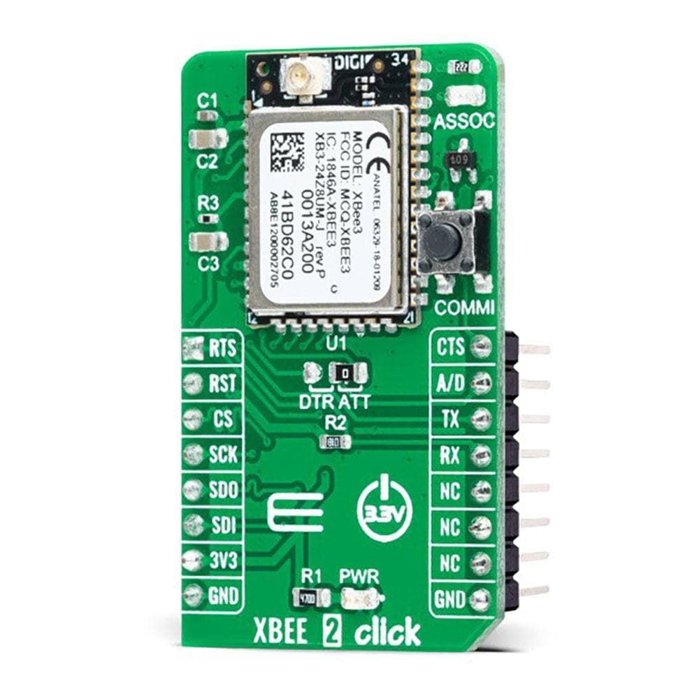
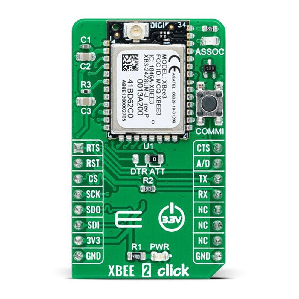
The XBee 2 Click Board™ is a compact add-on board providing wireless end-point connectivity to other devices. This board features the XB3-24Z8UM, a Digi XBee® 3 transceiver module offering a fully interoperable ecosystem covering all vertical markets from Digi International. Building on industry-leading technology, the pre-certified Digi XBee® 3 module delivers the flexibility to switch between multiple frequencies and wireless protocols as needed (Zigbee, 802.15.4, DigiMesh® and BLE). It can be easily configured and controlled from a simple, central platform and comes with built-in Digi TrustFence® security, identity, and data privacy features which use more than 175 controls to protect against new and evolving cyber threats. This Click board™ is suitable for broad smart-energy applications, wireless alarms and security, building automation, and others.
The XBee 2 Click Board™ is supported by a mikroSDK compliant library, which includes functions that simplify software development. This Click board™ comes as a thoroughly tested product, ready to be used on a system equipped with the mikroBUS™ socket.
How Does The XBee 2 Click Board™ Work?
The XBee 2 Click Board™ is based on the XB3-24Z8UM, a Digi XBee® 3 Zigbee 3.0 transceiver module providing wireless end-point connectivity from Digi International. This module uses the IEEE 802.15.4 networking protocol for fast point-to-multipoint or peer-to-peer networking designed for high-throughput applications requiring low latency and predictable communication timing. Building on industry-leading technology, the pre-certified XB3-24Z8UM module delivers the flexibility to switch between multiple frequencies and wireless protocols as needed (Zigbee, 802.15.4, DigiMesh®, and BLE), offering a fully interoperable ecosystem covering all vertical markets.
The XBee 2 Click Board™ comes with a configurable host interface allowing communication with MCU using the chosen interface. The XB3-24Z8UM can communicate with MCU using the UART interface with commonly used UART RX, TX, and hardware flow control pins UART CTS and RTS (Clear to Send and Ready to Send), or using the SPI interface (XBee module will work as an SPI-slave only). In the case of the SPI interface, the users can use it to configure the module and write the library by themselves. The XB3-24Z8UM also has built-in Digi TrustFence® security, identity, and data privacy features, employing more than 175 controls to protect against new and evolving cyber threats.
The XBee 2 Click Board™ is associated with many other features, such as the reset function and the possibility of visual and digital indicators. An active-low reset signal routed on the RST pin of the mikroBUS™ socket activates a hardware reset of the system, while a yellow LED indicator marked as ASSOC represents a visual indication of the module's connection to the network. If the LED is constantly on, it means that the module is not connected to the mobile network, while the case of standard flashing of the LED represents the normal operating mode.
The A/D pin routed on the INT pin of the mikroBUS™ socket represents a type of interrupt whose function can be selected by positioning an onboard SMD jumper to an appropriate position labelled as DTR or ATT. DTR position is a "Data terminal ready" function used to tell the XBee module that the host MCU is ready to communicate, while the ATT position (SPI Attention) represents an indicator for the SPI interface whenever the Xbee module has data for the host MCU. In addition, the board also has a commissioning pushbutton ,marked as COMMI which, combined with an ASSOC LED, provides various simple functions to aid in deploying devices in a network.
The XBee 2 Click Board™ can be operated only with a 3.3V logic voltage level. The board must perform appropriate logic voltage level conversion before using MCUs with different logic levels. However, the Click board™ comes equipped with a library containing functions and an example code that can be used, as a reference, for further development.
SPECIFICATIONS
| Type | ZigBee |
| Applications | Can be used for broad smart-energy applications, wireless alarms and security, building automation, and others |
| On-board modules | XB3-24Z8UM - Digi XBee® 3 Zigbee 3.0 radio module providing wireless end-point connectivity from Digi International |
| Key Features | Industry-leading technology, pre-certified, flexibility, multiple frequencies and wireless protocols, security features, high programmability, and more |
| Interface | SPI,UART |
| Compatibility | mikroBUS |
| Click board size | M (42.9 x 25.4 mm) |
| Supply Voltage | 3.3V |
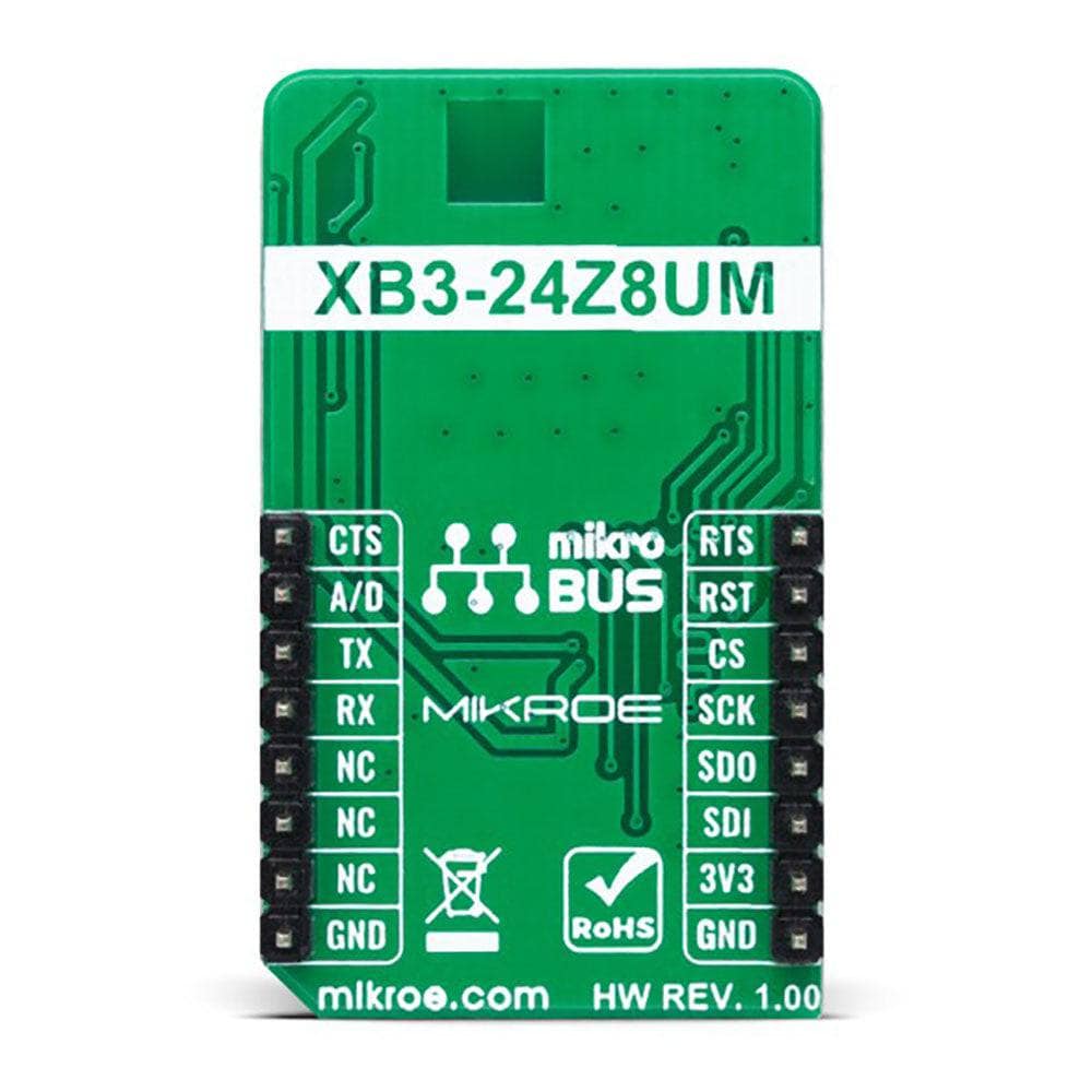
PINOUT DIAGRAM
This table shows how the pinout on the XBee 2 Click Board™ corresponds to the pinout on the mikroBUS™ socket (the latter shown in the two middle columns).
| Notes | Pin | Pin | Notes | ||||
|---|---|---|---|---|---|---|---|
| UART RTS | RTS | 1 | AN | PWM | 16 | CTS | UART CTS |
| Reset | RST | 2 | RST | INT | 15 | A/D | Data Ready Indicator |
| SPI Chip Select | CS | 3 | CS | RX | 14 | TX | UART TX |
| SPI Clock | SCK | 4 | SCK | TX | 13 | RX | UART RX |
| SPI Data OUT | SDO | 5 | MISO | SCL | 12 | NC | |
| SPI Data IN | SDI | 6 | MOSI | SDA | 11 | NC | |
| Power Supply | 3.3V | 7 | 3.3V | 5V | 10 | NC | |
| Ground | GND | 8 | GND | GND | 9 | GND | Ground |
ONBOARD SETTINGS AND INDICATORS
| Label | Name | Default | Description |
|---|---|---|---|
| LD1 | PWR | - | Power LED Indicator |
| LD2 | ASSOC | - | Associate LED Indicator |
| JP1 | - | Right | Data Ready Selection DTR/ATT: Left position DTR, Right position ATT |
| T1 | COMMI | - | Commissioning Button |
XBEE 2 CLICK ELECTRICAL SPECIFICATIONS
| Description | Min | Typ | Max | Unit |
|---|---|---|---|---|
| Supply Voltage | - | 3.3 | - | V |
| Frequency Range | - | 2.4 | - | GHz |
| Indoor/Urban Range | - | - | 60 | m |
| Outdoor/RF Line of Sight Range | - | - | 1200 | m |
| Data Rate | - | 250 | - | Kbps |
| Operating Temperature Range | -40 | +25 | +85 | °C |
Software Support
We provide a library for the XBee 2 Click Board™ as well as a demo application (example), developed using MikroElektronika compilers. The demo can run on all the main MikroElektronika development boards.
The package can be downloaded/installed directly from NECTO Studio The package Manager (recommended), downloaded from our LibStock™ or found on the MikroE Github account.
Library Description
This library contains API for XBee 2 Click driver.
Key functions
-
xbee2_get_serial_numberThis function sends a get serial number command. -
xbee2_set_device_nameThis function sets the device name (node identifier). -
xbee2_set_destination_addressThis function sets the destination address high and low bytes.
Example Description
This example demonstrates the use of the XBee 2 Click Board™ by showing the communication between the two Click Board™ boards configured in transparent mode.
void application_task ( void )
 {
 #ifdef DEMO_APP_TRANSMITTER
     xbee2_generic_write( &xbee2, DEMO_TEXT_MESSAGE, strlen( DEMO_TEXT_MESSAGE ) );
     log_printf( &logger, "%s", ( char * ) DEMO_TEXT_MESSAGE );
     Delay_ms( 3000 );
 #else
     xbee2_process( );
     if ( app_buf_len > 0 )
     {
         log_printf( &logger, "%s", app_buf );
         xbee2_clear_app_buf(  );
     }
 #endif
 }
The complete application code and ready-to-use projects can be installed directly from NECTO Studio The package Manager (recommended), downloaded from our LibStock™ or found on the MikroE Github account.
Other MikroE Libraries used in the example:
- MikroSDK.Board
- MikroSDK.Log
- Click.XBEE2
Additional Notes and Information
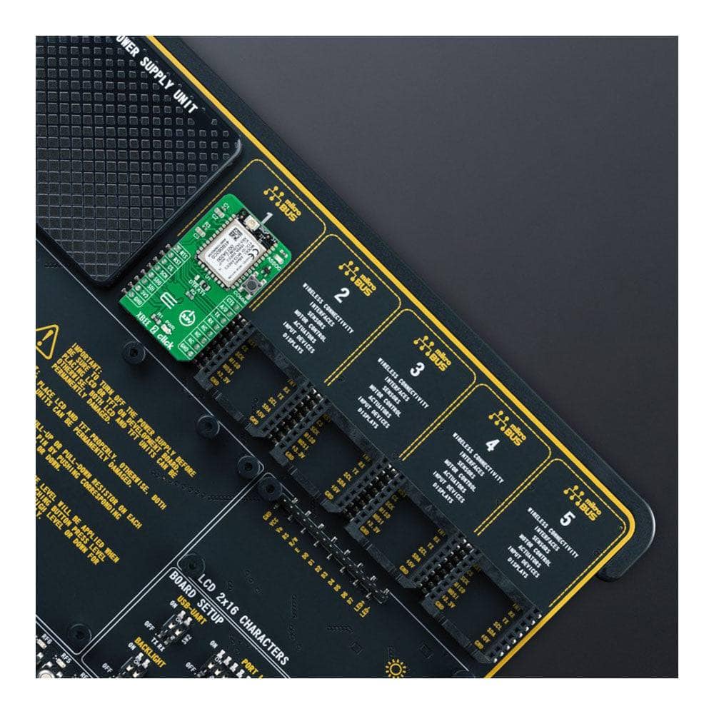
Depending on the development board you are using, you may need USB UART Click Board™, USB UART 2 Click or RS232 Click to connect to your PC, for development systems with no UART to USB interface available on the board. UART terminal is available in all MikroElektronika compilers.
MIKROSDK
The XBee 2 Click Board™ is supported with mikroSDK - MikroElektronika Software Development Kit. To ensure proper operation of mikroSDK compliant Click board™ demo applications, mikroSDK should be downloaded from the LibStock and installed for the compiler you are using.
XBee 2 Click Board
Frequently Asked Questions
Have a Question?
Be the first to ask a question about this.