


Mikroelektronika d.o.o.
SKU: MIKROE-5290LTE IoT 7 Click Board
LTE IoT 7 Click Board
Couldn't load pickup availability
Key Features
- End-to-end security with root of trust, integrated u-blox M10 GNSS receiver and CloudLocate, software-based configurability, simultaneous LTE communication with GNSS positioning, power efficient, global coverage, supporting a comprehensive set of 3GPP Rel. 14 features, over-the-air firmware updates, and more
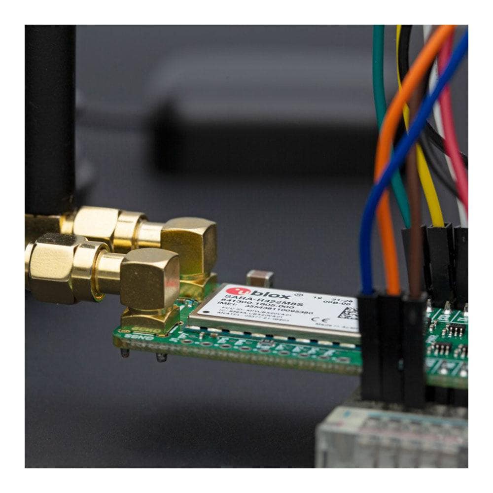
- Based on the SARA-R422M8S - multi-band LTE-M/NB-IoT/EGPRS multi-mode cellular module from u-blox
- Can be used for mission-critical IoT applications, as they include a unique and immutable root-of-trust, such as connected healthcare, industrial monitoring, point of sale and vending terminals, and many more
- mikroBUS: UART and GPIO Interfaces plus USB
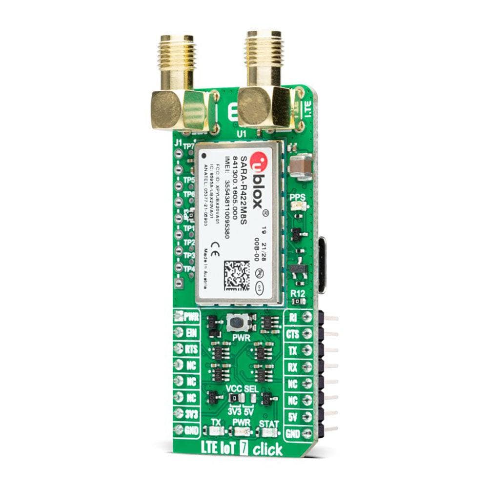
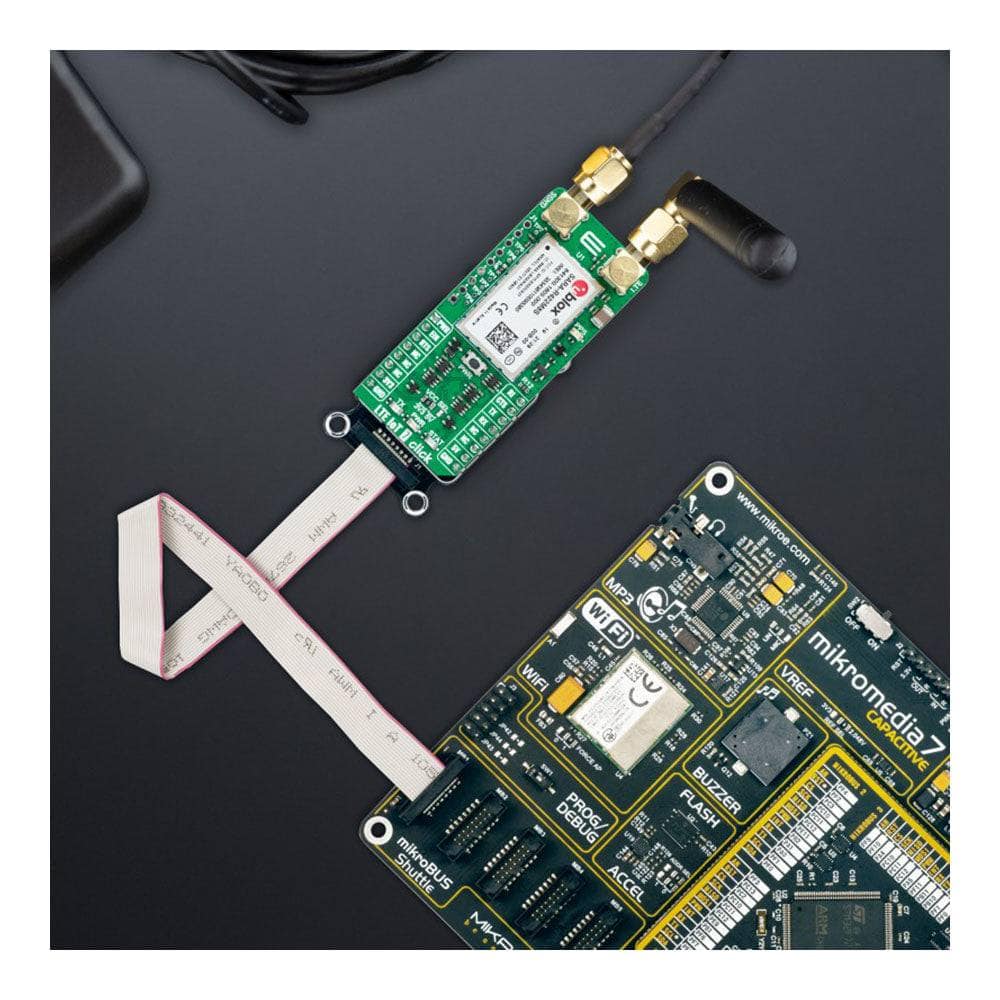
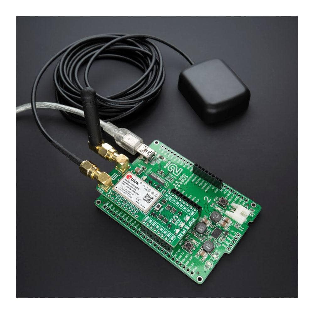
The LTE IoT 7 Click Board™ is an add-on board representing a secure-cloud multi-band solution designed for IoT applications. This board features the SARA-R422M8S, a multi-band LTE-M/NB-IoT/EGPRS multi-mode solution with integrated high-performance standard precision M8 GNSS receiver for global position acquisition from u-Blox. Equipped with familiar AT commands set over the UART interface, USB interface, and Network and Status indicators, it also provides over-the-air firmware updates, end-to-end trusted domain security, and u-Blox leading GNSS technology. This Click board™ is ideal for mission-critical IoT applications, as they include a unique and immutable root-of-trust, such as connected healthcare, industrial monitoring, point of sale and vending terminals, and many more.
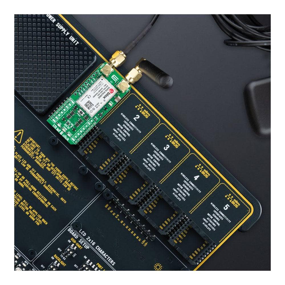
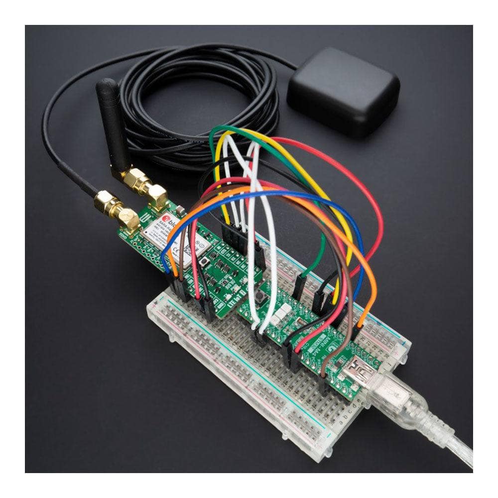
The LTE IoT 7 Click Board™ is supported by a mikroSDK compliant library, which includes functions that simplify software development. This Click board™ comes as a fully tested product, ready to be used on a system equipped with the mikroBUS™ socket.
How Does The LTE IoT 7 Click Board™ Work?
The LTE IoT 7 Click Board™ is based on the SARA-R422M8S, a multi-band LTE-M/NB-IoT/EGPRS multi-mode cellular module from u-blox. It comes in a miniature SARA LGA form factor module that is a drop-in migration from other u-blox cellular module families. The SARA-R422M8S modules provide software-based multi-band configurability enabling global coverage in LTE-M / NB-IoT and (E)GPRS radio access technologies, supporting a comprehensive set of 3GPP Rel. 14 features relevant for IoT applications.
The SARA-R422M8S module is ideal for mission-critical IoT solutions for its unique and immutable root-of-trust. It supports IoT Security-as-a-Service and provides the foundation for a trusted set of advanced security functionalities. The scalable, pre-shared key management system offers best-in-class data encryption and decryption, both on-device and from device-to-cloud. Utilizing the latest (D)TLS stack and cipher suites with hardware-based crypto acceleration provides robust, efficient, and protected communication.
This module requires a power supply of 3.8V. Therefore, the Click board™ incorporates an integrated buck (step-down DC-DC) converter, labelled as TPS7A7002 by Texas Instruments, which provides a stable 3.8V power supply, capable of mitigating voltage drops at the input when a high current peak appears (typically at the StartUp of the device).
The SARA-R422M8S communicates with MCU using the UART interface with commonly used UART RX and TX pins with the hardware flow control pins UART CTS, RTS, RI (Clear to Send, Ready to Send, and Ring Indicator). It operates at 115200 bps by default configuration to transmit and exchange data with the host MCU through AT commands that u-blox provides. It is also equipped with a USB type C connector, available for diagnostic purposes only. The module acts as a USB device and can be connected to any USB host equipped with compatible drivers.
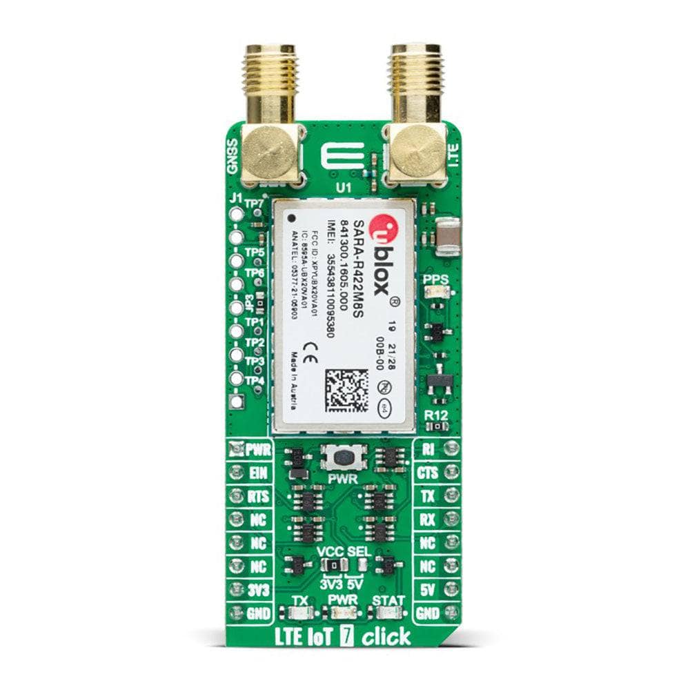
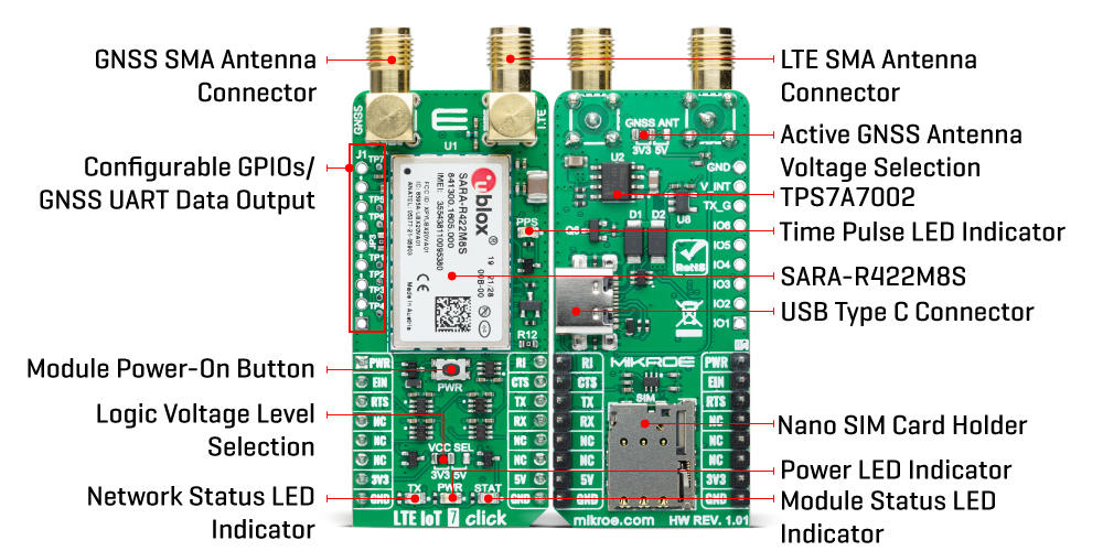
The push-button labelled PWR routed to the AN pin on the mikroBUS™ socket represents the Ignition (Power-On) button, where a yellow STAT LED indicates a successful action. If the device is already powered up, a LOW pulse with a duration of 1.5s on this pin will power the module down. Among its used pins, this Click board™ also has a GNSS external interrupt to control the GNSS receiver or to aid. It possesses three additional LED indicators: the yellow LED labelled as STAT used to indicate the Operational Status of the device visually, a red LED labelled as TX used to tell the Network Status, and an orange LED indicator marked as PPS used for time pulse signal information and indication.
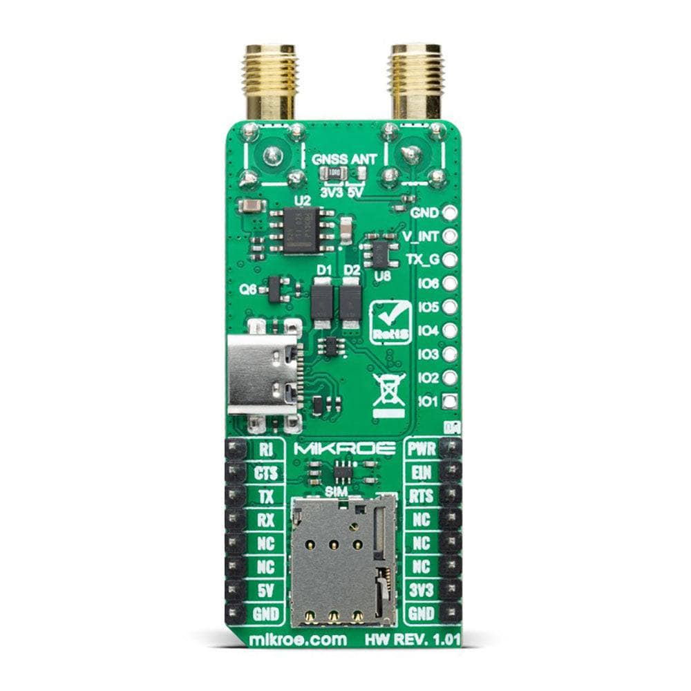
The GNSS RF input of the SARA-R422M8S, designed with 50Ω characteristic impedance and an internal DC block, is suitable for both active or passive GNSS antennas due to the built-in SAW filter followed by an LNA in front of the integrated high-performing u-blox M8 concurrent positioning engine. Besides those SMA connectors (for LTE and GNSS antennas), the LTE IoT 7 Click also has a Nano-SIM card slot that provides multiple connections and interface options. The J1 header allows you to access the configurable GPIO and GNSS Data output from internal u-blox GNSS, while test points labelled from TP1 to TP6 enable easy FW upgrades and testing of the module.
Customers can future-proof their solutions through over-the-air firmware updates, thanks to the uFOTA client/server solution that utilises LWM2M, a light and compact protocol ideal for IoT. As mentioned, we have also provided accessible test points directly connected to the TxD and RxD pins for FW upgrade purposes.
The LTE IoT 7 Click Board™ can operate with both 3.3V and 5V logic voltage levels selected via the VCC SEL jumper. This way, it is allowed for both 3.3V and 5V capable MCUs to use the communication lines properly. However, the Click board™ comes equipped with a library containing easy-to-use functions and an example code that can be used, as a reference, for further development.
SPECIFICATIONS
| Type | GPS/GNSS,LTE IoT |
| Applications | Can be used for mission-critical IoT applications, as they include a unique and immutable root-of-trust, such as connected healthcare, industrial monitoring, point of sale and vending terminals, and many more |
| On-board modules | SARA-R422M8S - multi-band LTE-M/NB-IoT/EGPRS multi-mode cellular module from u-blox |
| Key Features | End-to-end security with root of trust, integrated u-blox M10 GNSS receiver and CloudLocate, software-based configurability, simultaneous LTE communication with GNSS positioning, power efficient, global coverage, supporting a comprehensive set of 3GPP Rel. 14 features, over-the-air firmware updates, and more |
| Interface | GPIO, UART, USB |
| Compatibility | mikroBUS |
| Click board size | L (57.15 x 25.4 mm) |
| Input Voltage | 3.3V or 5V |
PINOUT DIAGRAM
This table shows how the pinout of the LTE IoT 7 Click Board™ corresponds to the pinout on the mikroBUS™ socket (the latter shown in the two middle columns).
| Notes | Pin | Pin | Notes | ||||
|---|---|---|---|---|---|---|---|
| Power-On | PWR | 1 | AN | PWM | 16 | RI | UART RI |
| GNSS Interrupt | EIN | 2 | RST | INT | 15 | CTS | UART CTS |
| UART RTS | RTS | 3 | CS | RX | 14 | TX | UART TX |
| NC | 4 | SCK | TX | 13 | RX | UART RX | |
| NC | 5 | MISO | SCL | 12 | NC | ||
| NC | 6 | MOSI | SDA | 11 | NC | ||
| Power Supply | 3.3V | 7 | 3.3V | 5V | 10 | 5V | Power Supply |
| Ground | GND | 8 | GND | GND | 9 | GND | Ground |
ONBOARD SETTINGS AND INDICATORS
| Label | Name | Default | Description |
|---|---|---|---|
| LD1 | PWR | - | Power LED Indicator |
| LD2 | TX | - | Network Status LED Indicator |
| LD3 | STAT | - | Module Status LED Indicator |
| LD4 | PPS | - | Time Pulse LED Indicator |
| JP1 | VCC SEL | Left | Logic Voltage Level Selection 3V3/5V: Left position 3V3, Right position 5V |
| JP2 | GNSS ANT | Left | Active GNSS Antenna Voltage Selection 3V3/5V: Left position 3V3, Right position 5V |
| JP3 | - | Populated | UART Data Terminal Ready / AUX UART Data Input (Active Low) |
| TP1 | - | - | UART Request to Send - Test point |
| TP2 | - | - | UART Clear to Send - Test point |
| TP3 | - | - | UART Data Output - Test point |
| TP4 | - | - | UART Data Input - Test point |
| TP5 | - | - | UART Data Set Ready / AUX UART Request to Send - Test point |
| TP6 | - | - | UART Data Carrier Detect / AUX UART Data Output - Test point |
| J1 | - | Unpopulated | Configurable GPIO |
LTE IOT 7 CLICK ELECTRICAL SPECIFICATIONS
| Description | Min | Typ | Max | Unit |
|---|---|---|---|---|
| Supply Voltage | 3.3 | - | 5 | V |
| Operating Frequency | 700 | - | 2100 | MHz |
| Operating Temperature Range | -20 | +25 | +65 | °C |
Software Support
We provide a library for the LTE IoT 7 Click Board™ as well as a demo application (example), developed using MikroElektronika compilers. The demo can run on all the main MikroElektronika development boards.
The package can be downloaded/installed directly from NECTO Studio The package Manager (recommended), downloaded from our LibStock™ or found on the MikroE Github account.
Library Description
This library contains API for LTE IoT 7 Click driver.
Key functions
-
lteiot7_set_sim_apnThis function sets APN for sim card. -
lteiot7_send_sms_textThis function sends text message to a phone number. -
lteiot7_parse_gpggaThis function parses the GPGGA data from the read response buffer.
Example Description
Application example shows device capable of connecting to the network and sending SMS or TCP/UDP messages, or retrieving data from GNSS using standard "AT" commands.
|
void application_task ( void ) |
The complete application code, and ready-to-usee projects can be installed directly from NECTO Studio. The package Manager (recommended), is downloaded from our LibStock™ or found on the MikroE Github account.
Other MikroE Libraries used in the example:
- MikroSDK.Board
- MikroSDK.Log
- Click.LTEIoT7
Additional Notes and Information
Depending on the development board you are using, you may need USB UART Click Board™, USB UART 2 Click or RS232 Click to connect to your PC, for development systems with no UART to USB interface available on the board. UART terminal is available in all MikroElektronika compilers.
MIKROSDK
The LTE IoT 7 Click Board™ is supported with mikroSDK - MikroElektronika Software Development Kit. To ensure proper operation of mikroSDK compliant Click board™ demo applications, mikroSDK should be downloaded from the LibStock and installed for the compiler you are using.
LTE IoT 7 Click Board
Frequently Asked Questions
Have a Question?
Be the first to ask a question about this.