


Mikroelektronika d.o.o.
SKU: MIKROE-5282Angle 6 Click Board
Angle 6 Click Board
Couldn't load pickup availability
Key Features
- Fast data acquisition, SPI serial interface, magnetic field strength detection, contactless sensing for long life, supported both end-of-shaft and off-axis, and many more
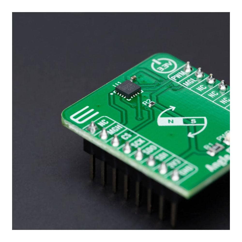
- Based on the MAQ470GQE - 12-bit contactless angle sensor with PWM output from Monolithic Power Systems
- Can be used as a highly reliable and contactless method to measure various applications' angles, position, and speed
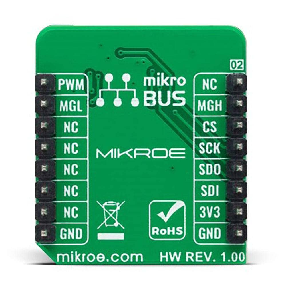
- mikroBUS: SPI and PWM Interfaces
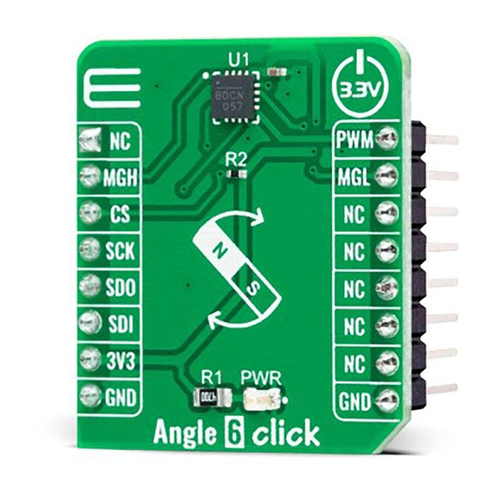
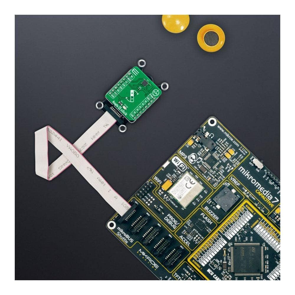
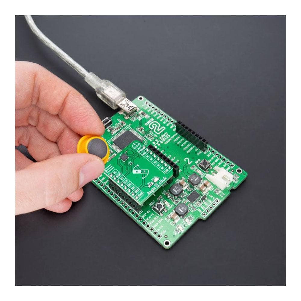
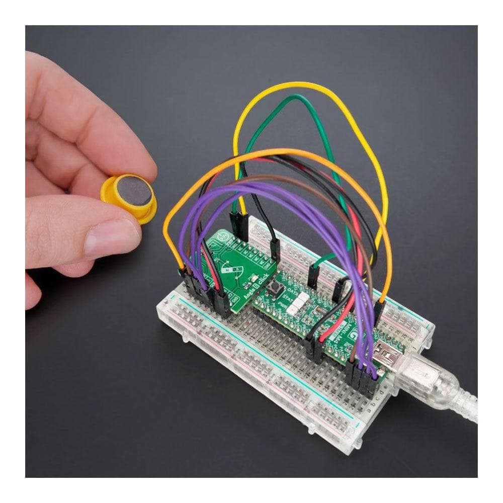
The Angle 6 Click Board™ is a compact add-on board that detects the absolute angular position of a permanent magnet, typically a diametrically magnetised cylinder on a rotating shaft. This board features the MAQ470GQE, a 12-bit contactless angle sensor with PWM output from Monolithic Power Systems. It supports many magnetic field strengths and spatial configurations, with both end-of-shaft and off-axis (side-shaft mounting) supported configurations. Fast data acquisition and processing provide accurate angle measurement at 0 to 60,000 rpm speeds, alongside magnetic field strength detection with programmable thresholds. This Click board™ offers a highly reliable and contactless method to measure various applications' angles, position, and speed.
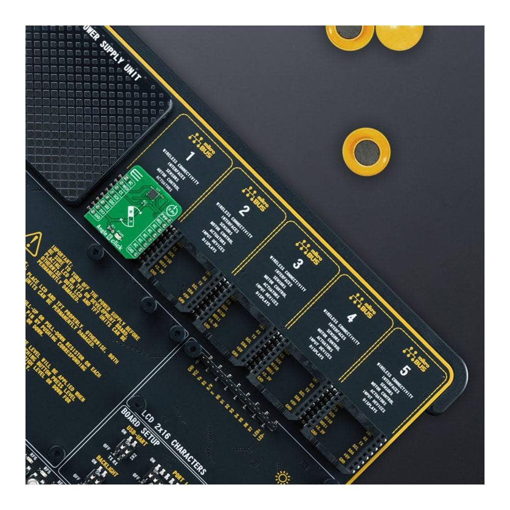
The Angle 6 Click Board™ supports the mikroSDK compliant library, which includes functions that simplify software development. This Click board™ comes as a thoroughly tested product, ready to be used on a system equipped with the mikroBUS™ socket.
How Does The Angle 6 Click Board™ Work?
The Angle 6 Click Board™ is based on the MAQ470GQE, 12-bit PWM output angle sensor that detects the absolute angular position of a permanent magnet, typically a diametrically magnetised cylinder on a rotating shaft from Monolithic Power Systems. It allows users to read angle position information and detect the speed or direction of magnet rotation. Fast data acquisition and processing provide accurate angle measurement at rates from 0 to 60,000rpm. It supports many magnetic field strengths and spatial configurations, with both end-of-shaft and off-axis (side-shaft mounting), supported configurations.

The MAQ470GQE features magnetic field strength detection with programmable thresholds to allow sensing of the magnet position relative to the sensor to create functions such as sensing axial movements or diagnostics. It can operate over a wide magnetic field range from 30mT to 150mT (60mT typical) with 5mT accuracy. Eight magnetic field thresholds are programmable in approximate 15mT steps allowing detection of changes in the distance between the magnet and the sensor. On-chip non-volatile memory provides storage for configuration parameters, including the reference zero angle position and magnetic field detection thresholds.
The magnetic field is detected with integrated Hall devices located in the sensors' centre. The angle is measured using the Spinaxis™ method, based on phase detection generating a sinusoidal signal with a phase representing the angle of the magnetic field. The angle is then obtained by a time-to-digital converter, representing output from the front-end to the digital conditioning block, which measures the time between the zero-crossing of the sinusoidal signal and the edge of a constant waveform. This output delivers a digital number proportional to the angle of the magnetic field at the rate of 1MHz in a straightforward and open-loop manner.
The Angle 6 Click Board™ communicates with MCU using the standard SPI serial interface for angle reading and register programming, which supports SPI Mode 0 and 3 and operates at clock rates up to 25 MHz. It also has the magnetic flags used to indicate when the sensor position's magnetic field is out of range, defined by the lower and upper magnetic field thresholds, routed on the RST and INT pins of the mikroBUS™ socket labelled as MGH and MGL.
The Angle 6 Click Board™ can be operated only with a 3.3V logic voltage level. The board must perform appropriate logic voltage level conversion before using MCUs with different logic levels. However, the Click board™ comes equipped with a library containing functions and an example code that can be used, as a reference, for further development.
SPECIFICATIONS
| Type | Magnetic |
| Applications | Can be used as a highly reliable and contactless method to measure various applications' angles, position, and speed |
| On-board modules | MAQ470GQE - 12-bit contactless angle sensor with PWM output from Monolithic Power Systems |
| Key Features | Fast data acquisition, SPI serial interface, magnetic field strength detection, contactless sensing for long life, supported both end-of-shaft and off-axis, and many more |
| Interface | PWM,SPI |
| Compatibility | mikroBUS |
| Click board size | S (28.6 x 25.4 mm) |
| Supply Voltage | 3.3V |
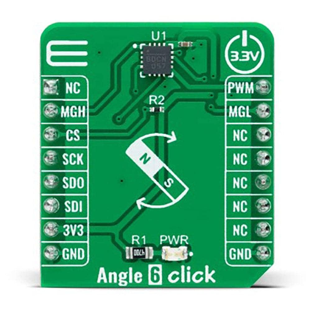
PINOUT DIAGRAM
This table shows how the pinout of the Angle 6 Click Board™ corresponds to the pinout on the mikroBUS™ socket (the latter shown in the two middle columns).
| Notes | Pin | Pin | Notes | ||||
|---|---|---|---|---|---|---|---|
| NC | 1 | AN | PWM | 16 | PWM | PWM Signal | |
| Magnetic Field Strength Detection (HIGH) | MGH | 2 | RST | INT | 15 | MGL | Magnetic Field Strength Detection (LOW) |
| SPI Chip Select | CS | 3 | CS | RX | 14 | NC | |
| SPI Clock | SCK | 4 | SCK | TX | 13 | NC | |
| SPI Data OUT | SDO | 5 | MISO | SCL | 12 | NC | |
| SPI Data IN | SDI | 6 | MOSI | SDA | 11 | NC | |
| Power Supply | 3.3V | 7 | 3.3V | 5V | 10 | NC | |
| Ground | GND | 8 | GND | GND | 9 | GND | Ground |
ONBOARD SETTINGS AND INDICATORS
| Designator | Name | Default | Description: describe the user + list all options with respective descriptions |
|---|---|---|---|
| LD1 | PWR | - | Power LED Indicator |
ANGLE 6 CLICK ELECTRICAL SPECIFICATIONS
| Description | Min | Typ | Max | Unit |
|---|---|---|---|---|
| Supply Voltage | - | 3.3 | - | V |
| Magnetic Filed Detection Range | 30 | 60 | 150 | mT |
| Magnetic Field Detection Accuracy | - | 5 | - | mT |
| Resolution | - | 12 | - | bit |
| Operation Temperature Range | -40 | - | +125 | bit °C |
Software Support
We provide a library for the Angle 6 Click Board™ and a demo application (example), developed using MikroElektronika compilers. The demo can run on all the main MikroElektronika development boards.
The package can be downloaded/installed directly from the NECTO Studio The package Manager (recommended), downloaded from our LibStock™ or found on the MikroE Github account.
Library Description
This library contains an API for the Angle 6 Click Board™ driver.
Standard key functions:
-
angle6_cfg_setupConfig Object Initialization function. -
angle6_initInitialisation function. -
angle6_default_cfgClick the Default Configuration function.
Example key functions:
-
angle6_write_registerThis function writes a data byte to the selected register by using SPI serial interface. -
angle6_read_registerThis function reads a data byte from the selected register by using SPI serial interface. -
angle6_read_angleThis function reads raw angle data and converts it to degrees.
Example Description
This example demonstrates the use of the Angle 6 Click Board™ by reading and displaying the magnet's angular position in degrees.
void application_task ( void )
{
    float angle = 0;
    if ( ANGLE6_OK == angle6_read_angle ( &angle6, &angle ) )
    {
        log_printf ( &logger, " Angle: %.2f Deg rnn", angle );
        Delay_ms ( 100 );
    }
}
The complete application code and ready-to-use projects can be installed directly from NECTO Studio The package Manager (recommended), downloaded from our LibStock™ or found on the MikroE Github account.
Other MikroE Libraries used in the example:
- MikroSDK.Board
- MikroSDK.Log
- Click.Angle6
Additional Notes and Information
Depending on the development board you are using, you may need a USB UART Click Board™, USB UART 2 Click or RS232 Click to connect to your PC, for development systems with no UART to USB interface available on the board. UART terminal is available in all MikroElektronika compilers.
MIKROSDK
The Angle 6 Click Board™ is supported with mikroSDK - MikroElektronika Software Development Kit. To ensure proper operation of mikroSDK compliant Click board™ demo applications, mikroSDK should be downloaded from the LibStock and installed for the compiler you are using.
Angle 6 Click Board
Frequently Asked Questions
Have a Question?
Be the first to ask a question about this.