


Mikroelektronika d.o.o.
Expand 14 Click Board™
Expand 14 Click Board™
SKU: MIKROE-5241
Couldn't load pickup availability


Key Features
Overview
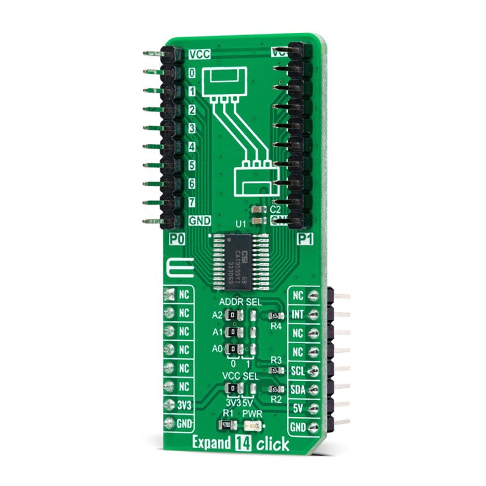
The Expand 14 Click Board™ is a compact add-on board that contains a multi-port I/O expander. This board features the CAT9555, a CMOS device that provides 16-bit parallel input/output port expansion from ON Semiconductor. The CAT9555 contains two 8-bit configuration ports (input or output), input, output, and polarity inversion registers, alongside an I2C-compatible serial interface. Any sixteen I/Os can be configured as an input or output by writing to the configuration register. It also features an active-low interrupt output, indicating to the host controller that an input state has been changed. This Click board™ provides a simple solution when additional I/Os are needed while keeping interconnections to a minimum in system monitoring applications, industrial controllers, portable equipment, and many more.
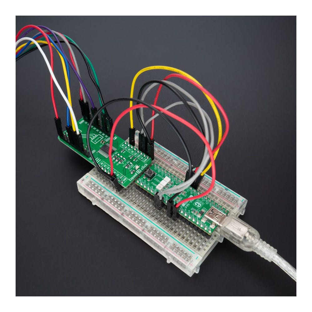
The Expand 14 Click Board™ is supported by a mikroSDK compliant library, including functions that simplify software development. This Click board™ comes as a thoroughly tested product, ready to be used on a system equipped with the mikroBUS™ socket.
Downloads
How Does The Expand 14 Click Board™ Work?
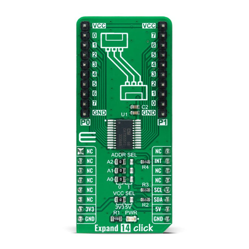
The Expand 14 Click Board™ as its foundation uses the CAT9555, a general-purpose I/O expander from ON Semiconductor. It contains two 8-bit configuration ports (input or output), input, output, and polarity inversion registers, alongside an I2C-compatible serial interface, where any of the sixteen I/Os can be configured as an input or output by writing to the configuration register. This port expander represents a simple solution when additional I/Os are needed while keeping interconnections to a minimum; particularly great for sensors, power switches, LEDs, pushbuttons, and fans.
Each I/O port is 5V input tolerant, with a high current I/O drive sink of up to 25mA and an I/O source of up to 10mA, maximum. Additionally, each I/O port is compatible with logic thresholds of 2.5V, 3.3V, and 5V.
The Expand 14 Click Board™ communicates with MCU using the standard I2C 2-Wire interface with a maximum clock frequency of 400kHz. The CAT9555 has a 7-bit slave address with the first four MSBs fixed to 0100. The address pins A0, A1, and A2, are programmed by the user and determine the value of the last three LSBs of the slave address, which can be selected by positioning onboard SMD jumpers labelled as ADDR SEL to an appropriate position marked as 0 or 1.
Besides, it also features an active-low interrupt feature, routed to the INT pin of the mikroBUS™ socket, indicating to the host controller that an input state has been changed.
The Expand 14 Click Board™ can operate with both 3.3V and 5V logic voltage levels selected via the VCC SEL jumper. This way, it is allowed for both 3.3V and 5V capable MCUs to use the communication lines properly. However, the Click board™ comes equipped with a library containing easy-to-use functions and an example code that can be used, as a reference, for further development.
SPECIFICATIONS
| Type | Port expander |
| Applications | Can be used for sensors, power switches, LEDs, pushbuttons, and fans |
| On-board modules | CAT9555 - general-purpose I/O expander from ON Semiconductor |
| Key Features | 16 I/O Pins that default to inputs at Power−Up, 5V Tolerant I/Os, high drive capability, individual I/O configuration, polarity inversion register, interrupt, and more |
| Interface | I2C |
| Compatibility | mikroBUS |
| Click board size | L (57.15 x 25.4 mm) |
| Input Voltage | 3.3V or 5V |
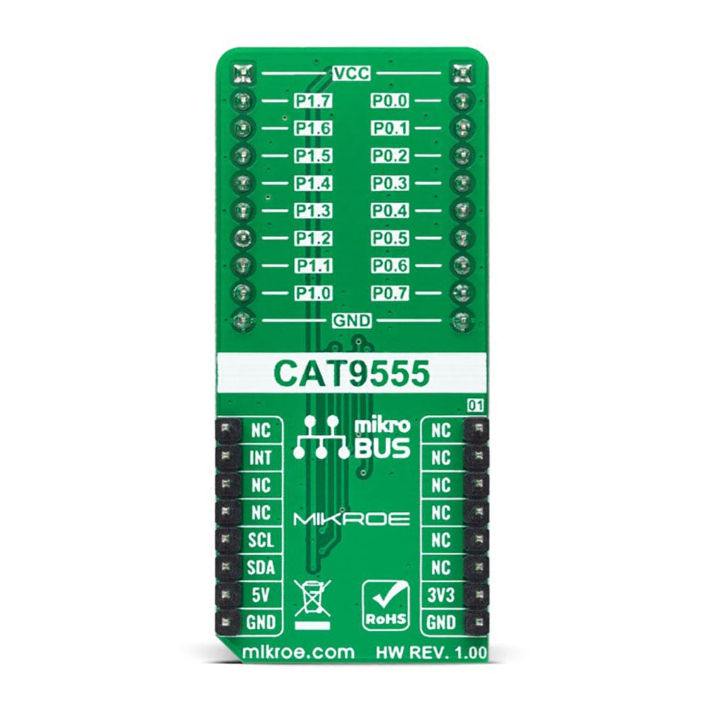
PINOUT DIAGRAM
This table shows how the pinout of the Expand 14 Click Board™ corresponds to the pinout on the mikroBUS™ socket (the latter shown in the two middle columns).
| Notes | Pin | Pin | Notes | ||||
|---|---|---|---|---|---|---|---|
| NC | 1 | AN | PWM | 16 | NC | ||
| NC | 2 | RST | INT | 15 | INT | Interrupt | |
| NC | 3 | CS | RX | 14 | NC | ||
| NC | 4 | SCK | TX | 13 | NC | ||
| NC | 5 | MISO | SCL | 12 | SCL | I2C Clock | |
| NC | 6 | MOSI | SDA | 11 | SDA | I2C Data | |
| Power Supply | 3.3V | 7 | 3.3V | 5V | 10 | 5V | Power Supply |
| Ground | GND | 8 | GND | GND | 9 | GND | Ground |
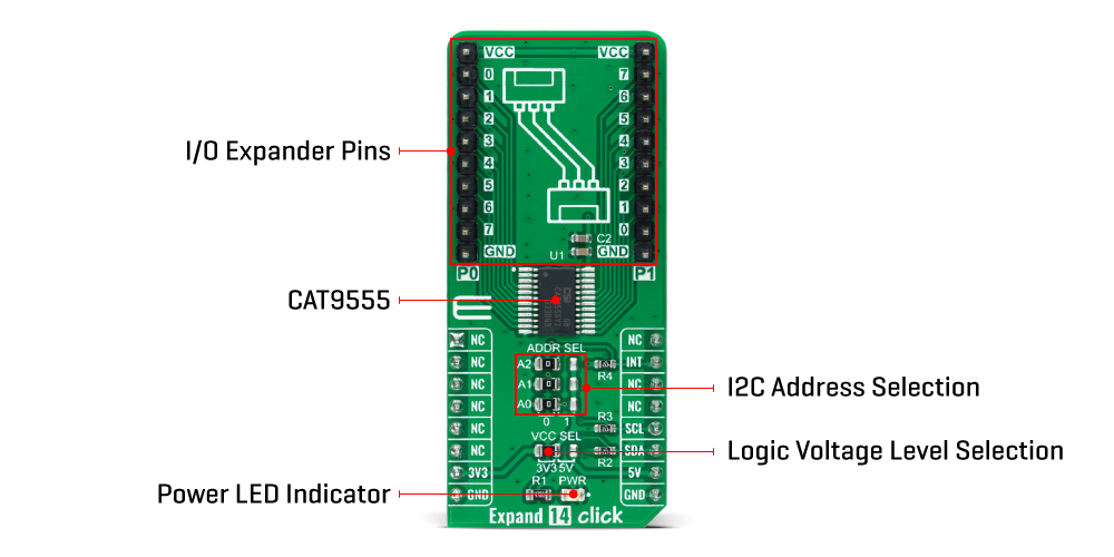
ONBOARD SETTINGS AND INDICATORS
| Label | Name | Default | Description |
|---|---|---|---|
| LD1 | PWR | - | Power LED Indicator |
| JP1 | VCC SEL | Left | Logic Level Voltage Selection 3V3/5V: Left position 3V3, Right position 5V |
| JP2-JP4 | ADDR SEL | Left | I2C Address Selection 0/1: Left position 0, Right position 1 |
| J1-J2 | P0-P1 | Populated | I/O Expander Ports |
EXPAND 14 CLICK ELECTRICAL SPECIFICATIONS
| Description | Min | Typ | Max | Unit |
|---|---|---|---|---|
| Supply Voltage | 3.3 | - | 5 | V |
| Output Current - Source/Sink | - | 10/24 | - | mA |
| Number of I/Os | - | - | 16 | pins |
| Operating Temperature Range | -40 | +25 | +85 | °C |
| General Information | |
|---|---|
Part Number (SKU) |
MIKROE-5241
|
Manufacturer |
|
| Physical and Mechanical | |
Weight |
0.02 kg
|
| Other | |
EAN |
8606027388194
|
Frequently Asked Questions
Have a Question?
Be the first to ask a question about this.