


Mikroelektronika d.o.o.
SKU: MIKROE-5239Hall Current 14 Click Board
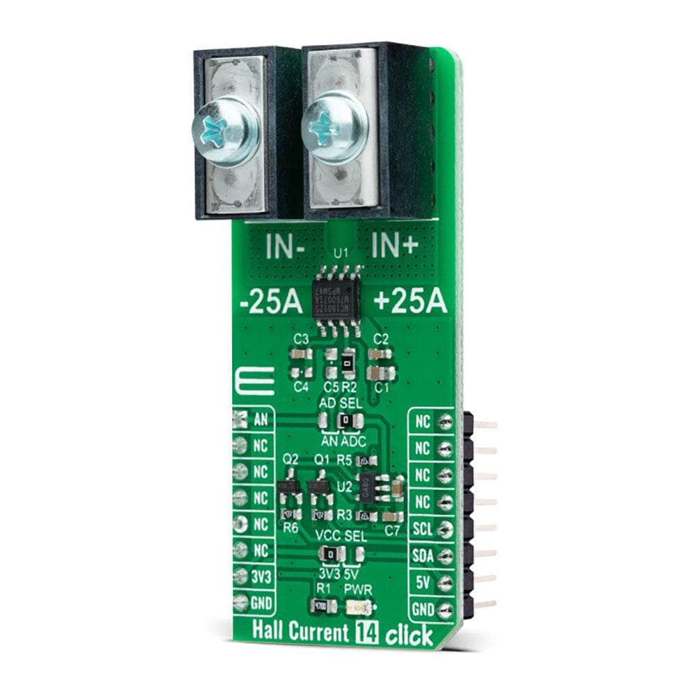
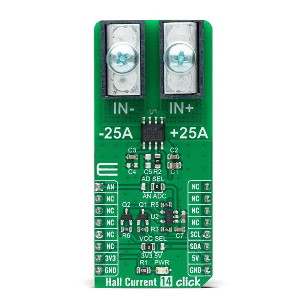
Hall Current 14 Click Board
Couldn't load pickup availability
Key Features
- Output voltage proportional to AC or DC currents, ratiometric output from supply voltage, high reliability, factory-trimmed for accuracy, possibility of signal processing in analog and digital form, immune to external magnetic fields by differential sensing, and more
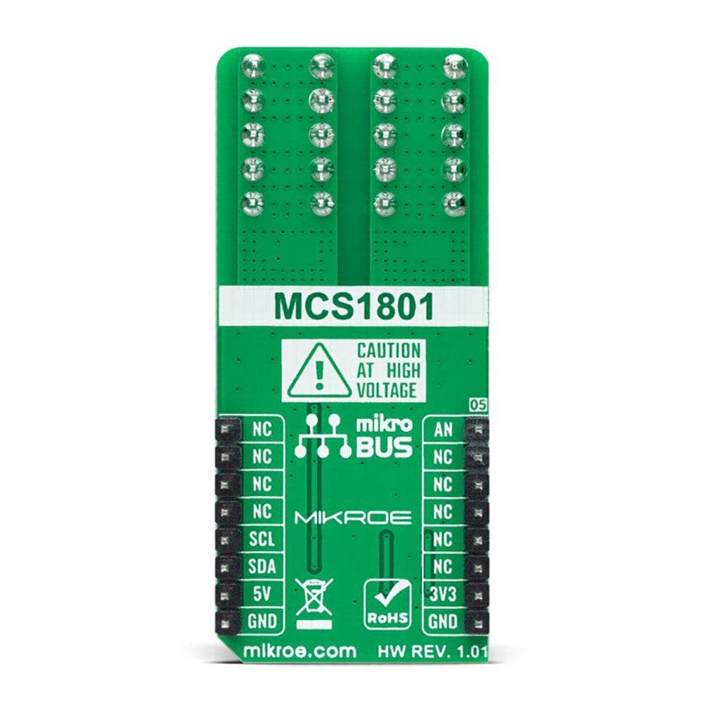
- Based on the MCS1801 - linear Hall-effect current sensor for AC or DC current sensing from Monolithic Power Systems (MPS)
- Can be used for applications requiring a combination of high-current monitoring and high isolation voltage between the primary high-current and low-voltage sides
- mikroBUS: I2C and Analogue Interfaces
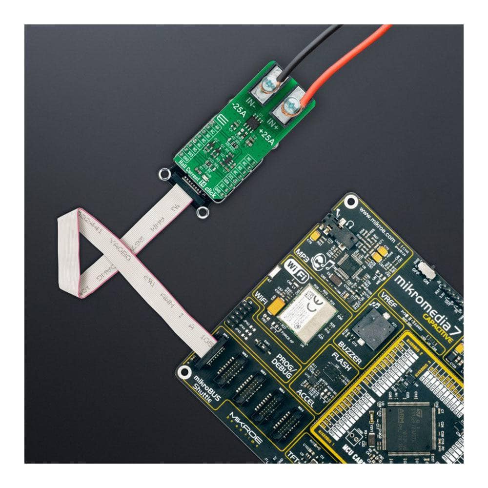
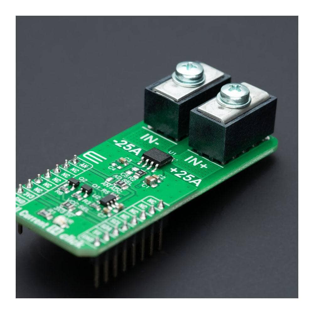
The Hall Current 14 Click Board™ is a compact add-on board that contains a precise solution for AC/DC current sensing. This board features the MCS1801, a fully integrated Hall-effect-based isolated linear current sensor designed for the current range of ±25A from Monolithic Power Systems (MPS). The galvanic isolation between the pins of the primary copper conductive path and the sensor leads allows the MCS1801 to replace optoisolators or other isolation devices. Applied current flowing through this copper conduction path generates a magnetic field that the differential Hall sensors convert into a proportional voltage, where after that, the user is given the option to process the output voltage as an analogue or digital value. This Click board™ is ideal for applications requiring a combination of high-current monitoring and high isolation voltage between the primary high-current and low-voltage sides.
The Hall Current 14 Click Board™ is supported by a mikroSDK compliant library, which includes functions that simplify software development. This Click board™ comes as a fully tested product, ready to be used on a system equipped with the mikroBUS™ socket.
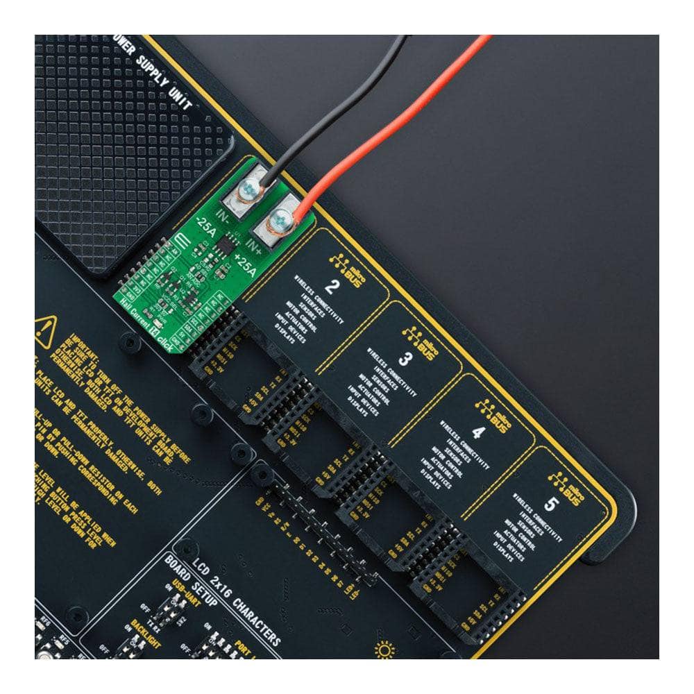
 DO NOT TOUCH THE BOARD WHILE THE LOAD IS CONNECTED!
Note: This Click board™ needs to be used by trained personnel only while applying high voltages. Special care should be taken when working with hazardous voltage levels.
How Does The Hall Current 14 Click Board™ Work?
The Hall Current 14 Click Board™ as its foundation uses the MCS1801, a Hall-effect current sensor that sends an analog voltage proportional to the magnetic field intensity caused by the current flowing through the primary input conductor from Monolithic Power Systems (MPS). Immune to external magnetic fields by differential sensing, the MCS1801 can detect both DC and AC designed for the current range of ±25A. Device accuracy, ±3%, is optimized across the operating ambient temperature through the close proximity of the magnetic signal to the Hall sensors.
A primary conductor with a low resistance allows current to flow close to the IC, containing high-accuracy Hall-effect sensors. This current generates a magnetic field sensed at two different points by the integrated Hall-effect transducers. The magnetic field difference between these two points is then converted into a voltage (analog output) proportional to the applied current.
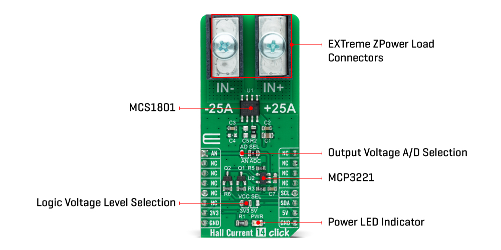
The analog output signal of the MCS1801 can be converted to a digital value using MCP3221, a successive approximation A/D converter with a 12-bit resolution from Microchip using a 2-wire I2C compatible interface, or can be sent directly to an analog pin of the mikroBUS™ socket labelled as AN. Selection can be performed by onboard SMD jumper labelled as AD SEL to an appropriate position marked as AN and ADC.
The MCP3221 provides one single-ended input with low power consumption, a low maximum conversion current, and a Standby current of 250μA and 1μA, respectively. Data can be transferred at rates of up to 100kbit/s in the Standard and 400kbit/s in the Fast Mode. Also, maximum sample rates of 22.3kSPS with the MCP3221 are possible in a Continuous-Conversion Mode with a clock rate of 400kHz.
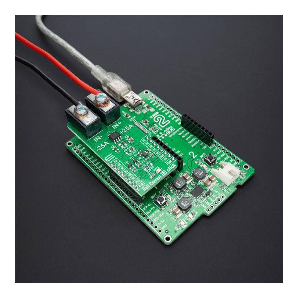
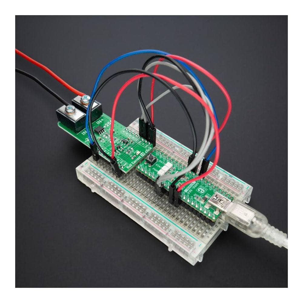
Also, this Click board™ should be connected in series with the load. The current is measured by two onboard terminal connectors, one terminal block for the positive and the other for the negative current input.
The Hall Current 14 Click Board™ can operate with both 3.3V and 5V logic voltage levels selected via the VCC SEL jumper. This way, it is allowed for both 3.3V and 5V capable MCUs to use the communication lines properly. However, the Click board™ comes equipped with a library containing easy-to-use functions and an example code that can be used, as a reference, for further development.
SPECIFICATIONS
| Type | Current sensor |
| Applications | Can be used for applications requiring a combination of high-current monitoring and high isolation voltage between the primary high-current and low-voltage sides |
| On-board modules | MCS1801 - linear Hall-effect current sensor for AC or DC current sensing from Monolithic Power Systems (MPS) |
| Key Features | Output voltage proportional to AC or DC currents, ratiometric output from supply voltage, high reliability, factory-trimmed for accuracy, possibility of signal processing in analog and digital form, immune to external magnetic fields by differential sensing, and more |
| Interface | Analog,I2C |
| Compatibility | mikroBUS |
| Click board size | L (57.15 x 25.4 mm) |
| Input Voltage | 3.3V or 5V |
PINOUT DIAGRAM
This table shows how the pinout of the Hall Current 14 Click Board™ corresponds to the pinout on the mikroBUS™ socket (the latter shown in the two middle columns).
| Notes | Pin | Pin | Notes | ||||
|---|---|---|---|---|---|---|---|
| Analog Signal | AN | 1 | AN | PWM | 16 | NC | |
| NC | 2 | RST | INT | 15 | NC | ||
| NC | 3 | CS | RX | 14 | NC | ||
| NC | 4 | SCK | TX | 13 | NC | ||
| NC | 5 | MISO | SCL | 12 | SCL | I2C Clock | |
| NC | 6 | MOSI | SDA | 11 | SDA | I2C Data | |
| Power Supply | 3.3V | 7 | 3.3V | 5V | 10 | 5V | Power Supply |
| Ground | GND | 8 | GND | GND | 9 | GND | Ground |
ONBOARD SETTINGS AND INDICATORS
| Label | Name | Default | Description |
|---|---|---|---|
| LD1 | PWR | - | Power LED Indicator |
| JP1 | VCC SEL | Left | Logic Level Voltage Selection 3V3/5V: Left position 3V3, Right position 5V |
| JP2 | AD SEL | Right | Output Voltage A/D Selection AN/ADC: Left position AN, Right position ADC |
HALL CURRENT 14 CLICK ELECTRICAL SPECIFICATIONS
| Description | Min | Typ | Max | Unit |
|---|---|---|---|---|
| Supply Voltage | 3.3 | - | 5 | V |
| Measurement Range | -25 | - | +25 | A |
| Sensitivity | - | 80 | - | mV/A |
| Isolation Working Voltage | - | 200 | - | VRMS |
| Operating Temperature Range | -40 | +25 | +120 | °C |
Software Support
We provide a library for the Hall Current 14 Click Board™ as well as a demo application (example), developed using MikroElektronika compilers. The demo can run on all the main MikroElektronika development boards.
The package can be downloaded/installed directly from NECTO Studio The package Manager (recommended), downloaded from our LibStock™ or found on MikroE Github account.
Library Description
This library contains API for the Hall Current 14 Click Board™ driver.
Key functions
-
hallcurrent14_read_voltageThis function reads raw ADC value and converts it to proportional voltage level. -
hallcurrent14_set_vrefThis function sets the voltage reference for Hall Current 14 Click Board™ driver. -
hallcurrent14_read_currentThis function reads the input current level [A] based on @b HALLCURRENT14_NUM_CONVERSIONS of voltage measurements.
Example Description
This example demonstrates the use of the Hall Current 14 Click Board™ by reading and displaying the input current measurements.
void application_task ( void )
{
float current = 0;
if ( HALLCURRENT14_OK == hallcurrent14_read_current ( &hallcurrent14, ¤t ) )
{
log_printf( &logger, " Current : %.3f[A]rnn", current );
Delay_ms( 1000 );
}
}
The full application code, and ready to use projects can be installed directly from NECTO Studio The package Manager (recommended), downloaded from our LibStock™ or found on MikroE Github account.
Other MikroE Libraries used in the example:
- MikroSDK.Board
- MikroSDK.Log
- Click.HallCurrent14
Additional Notes and Information
Depending on the development board you are using, you may need a USB UART Click Board™, USB UART 2 Click or RS232 Click to connect to your PC, for development systems with no UART to USB interface available on the board. UART terminal is available in all MikroElektronika compilers.
MIKROSDK
The Hall Current 14 Click Board™ is supported with mikroSDK - MikroElektronika Software Development Kit. To ensure proper operation of mikroSDK compliant Click board™ demo applications, mikroSDK should be downloaded from the LibStock and installed for the compiler you are using.
Hall Current 14 Click Board
Frequently Asked Questions
Have a Question?
Be the first to ask a question about this.