


Mikroelektronika d.o.o.
Angle 7 Click Board™
Angle 7 Click Board™
SKU: MIKROE-5196
Couldn't load pickup availability
Key Features
Overview
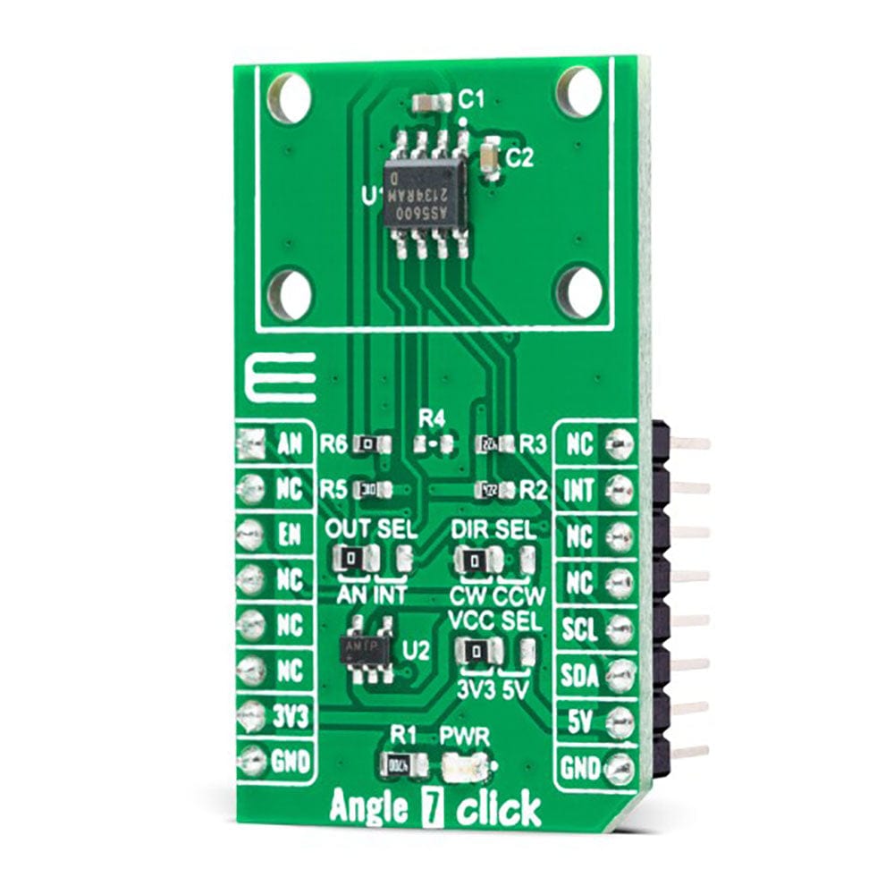
The Angle 7 Click Board™ is a compact add-on board that detects the absolute angular position of a permanent magnet. This board features the AS5600, a programmable Hall-based rotary magnetic position sensor with a high-resolution 12-bit analogue or PWM output from AMS AG. Based on planar Hall technology, this sensor measures the orthogonal component of the flux density (Bz) from an external magnet while rejecting stray magnetic fields. The default range of the output is from 18 to 360 degrees, where the full resolution of the device can be applied to a smaller range by programming a zero angle (start position) and a maximum angle (Stop position) through the I2C interface used for configuration and user programming of non-volatile parameters. This Click board™ is suitable for contactless potentiometers, contactless knobs, RC servos, and other angular position measurement solutions.
The Angle 7 Click Board™ is supported by a mikroSDK compliant library, which includes functions that simplify software development. This Click board™ comes as a fully tested product, ready to be used on a system equipped with the mikroBUS™ socket.
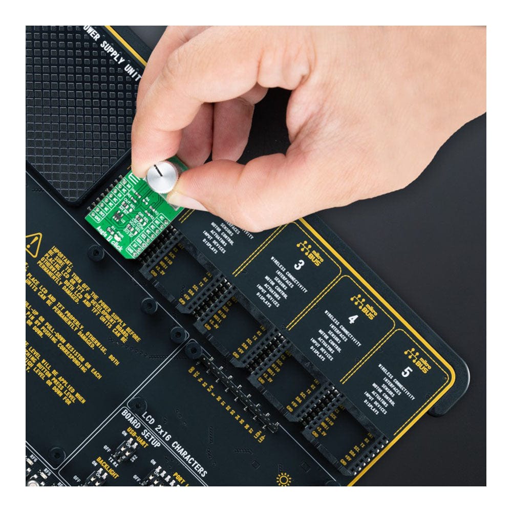
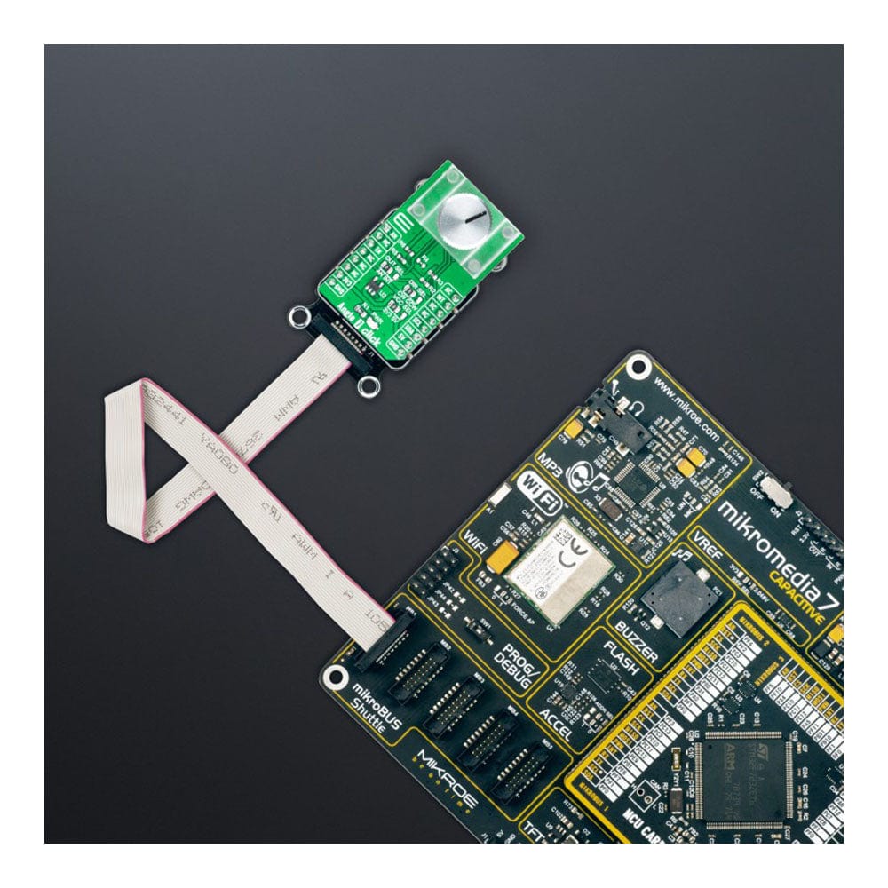
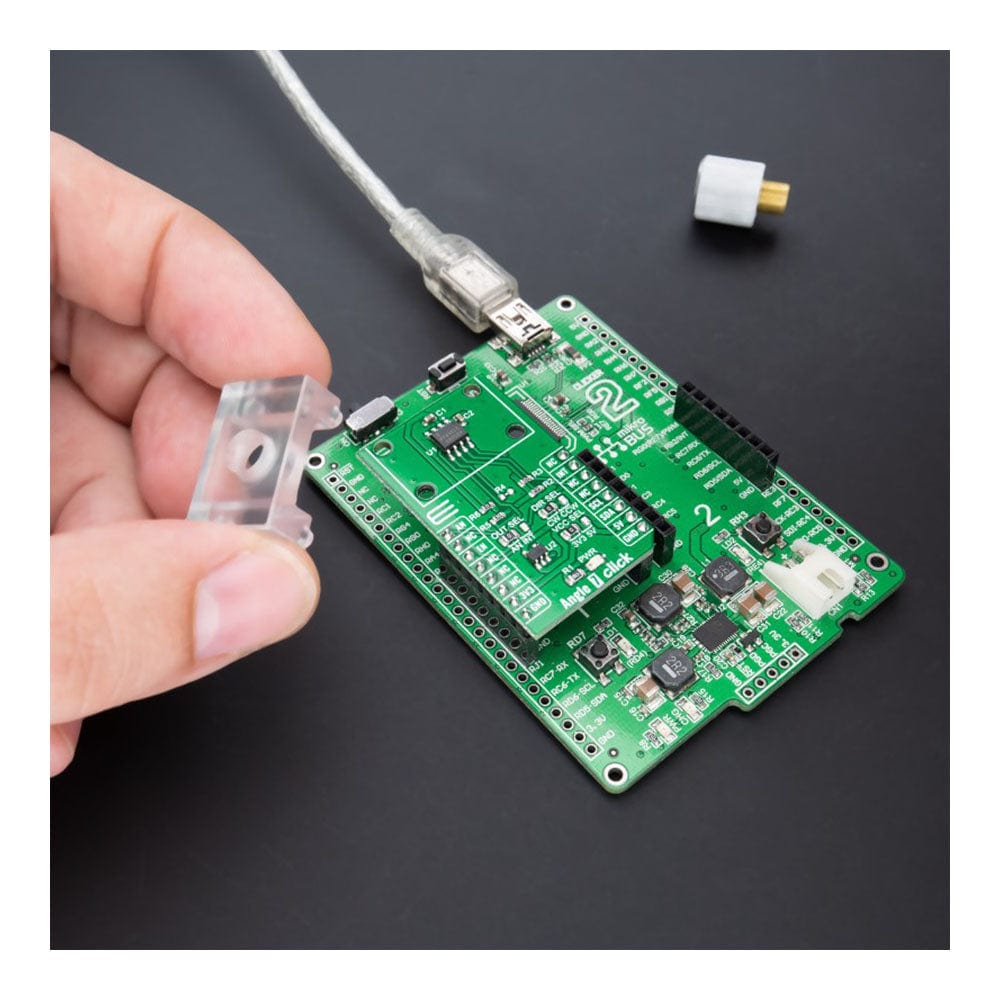
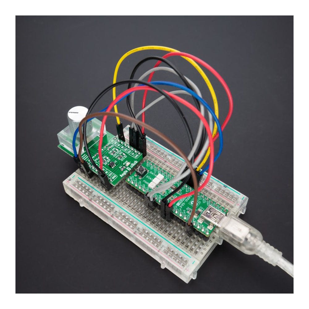
Note: The Click Board does not include the magnet, holder or control knob. This is shown as an example application.
Downloads
How Does The Angle 7 Click Board™ Work?
The Angle 7 Click Board™ as its foundation uses the AS5600, an easy to program magnetic rotary position sensor with a high-resolution 12-bit analog or PWM output from AMS AG. The AS5600 is a Hall-based rotary magnetic position sensor using planar sensors that convert the magnetic field component perpendicular to the surface of the chip into a voltage. It measures the absolute angle of a diametric-magnetized on-axis magnet while at the same time rejecting stray magnetic fields. By default, the output represents a range from 18 to 360 degrees. It is also possible to define a smaller range to the output by programming a zero angle (start position) and a maximum angle (stop position).
The signals coming from internal Hall sensors are first amplified and filtered before their conversion by the ADC and then processed by the hardwired CORDIC block to compute the angle and magnitude of the magnetic field vector. The intensity of the magnetic field is used by the automatic gain control (AGC) to adjust the amplification level to compensate for temperature and magnetic field variations. After that, the output stage uses the angle value provided by the CORDIC algorithm. The user can choose between an analog output representing the angle as a ratiometric linear absolute value and a digital PWM-encoded output representing the angle as the pulse width. The selection can be made by positioning the SMD jumper labelled as OUT SEL in an appropriate position marked as AN or INT.
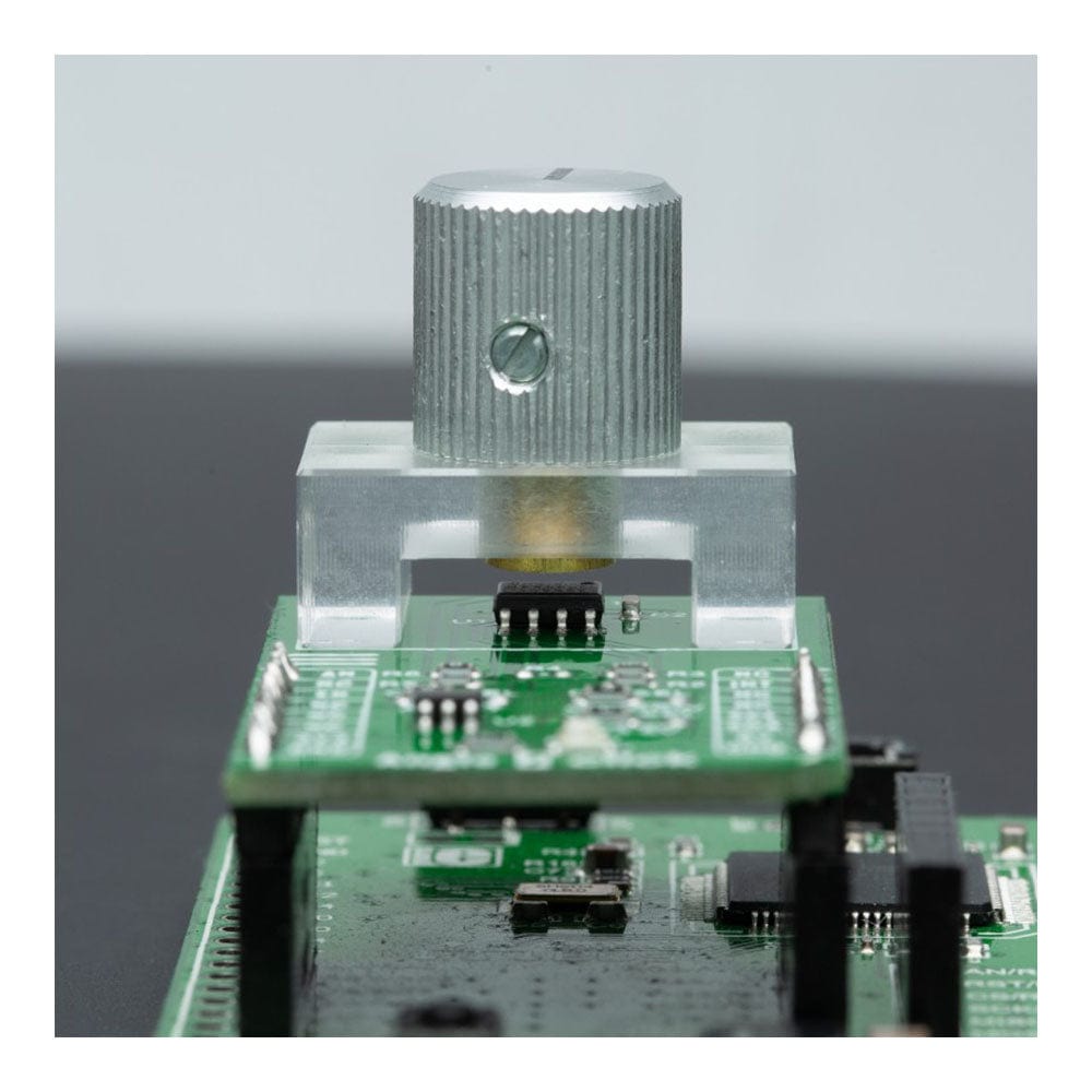
The Angle 7 Click Board™ communicates with MCU using the standard I2C 2-Wire interface with a maximum clock frequency of 1MHz, fully adjustable through software registers. Also, the DIR SEL jumper allows users to select the polarity of the output relative to rotation direction by positioning the SMD jumper in an appropriate position marked as CW or CCW allowing clockwise or counterclockwise rotation. A unique addition to this board is a position for a rotary magnet holder designed to be used alongside a magnetic rotary position sensor allowing fast prototyping and quick measurements during development.
The Angle 7 Click Board™ can operate with both 3.3V and 5V logic voltage levels selected via the VCC SEL jumper. Both mikroBUS™ power rails have protection in the form of diode MAX40200, controllable through an EN pin on the mikroBUS™ socket to prevent any unwanted back voltage. This way, it is allowed for both 3.3V and 5V capable MCUs to use the communication lines properly. However, the Click board™ comes equipped with a library containing easy-to-use functions and an example code that can be used, as a reference, for further development.
NOTE: In the case of using a logic level of 5V, it is necessary first to remove the resistor R6 and only then switch the VCC jumper to the 5V position.
SPECIFICATIONS
| Type | Magnetic |
| Applications | Can be used for contactless potentiometers, contactless knobs, RC servos, and other angular position measurement solutions |
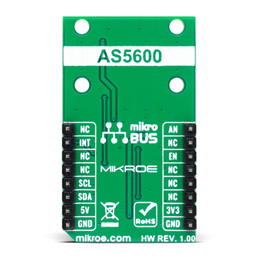
| On-board modules | AS5600 - rotary magnetic position sensor from ams AG |
| Key Features | Contactless angle measurement, highest reliability and durability, simple user-programmable start and stop positions over the I2C Interface, high-resolution output signal, great flexibility on angular excursion, selectable output, and more |
| Interface | Analog,I2C,PWM |
| Compatibility | mikroBUS |
| Click board size | M (42.9 x 25.4 mm) |
| Input Voltage | 3.3V or 5V |
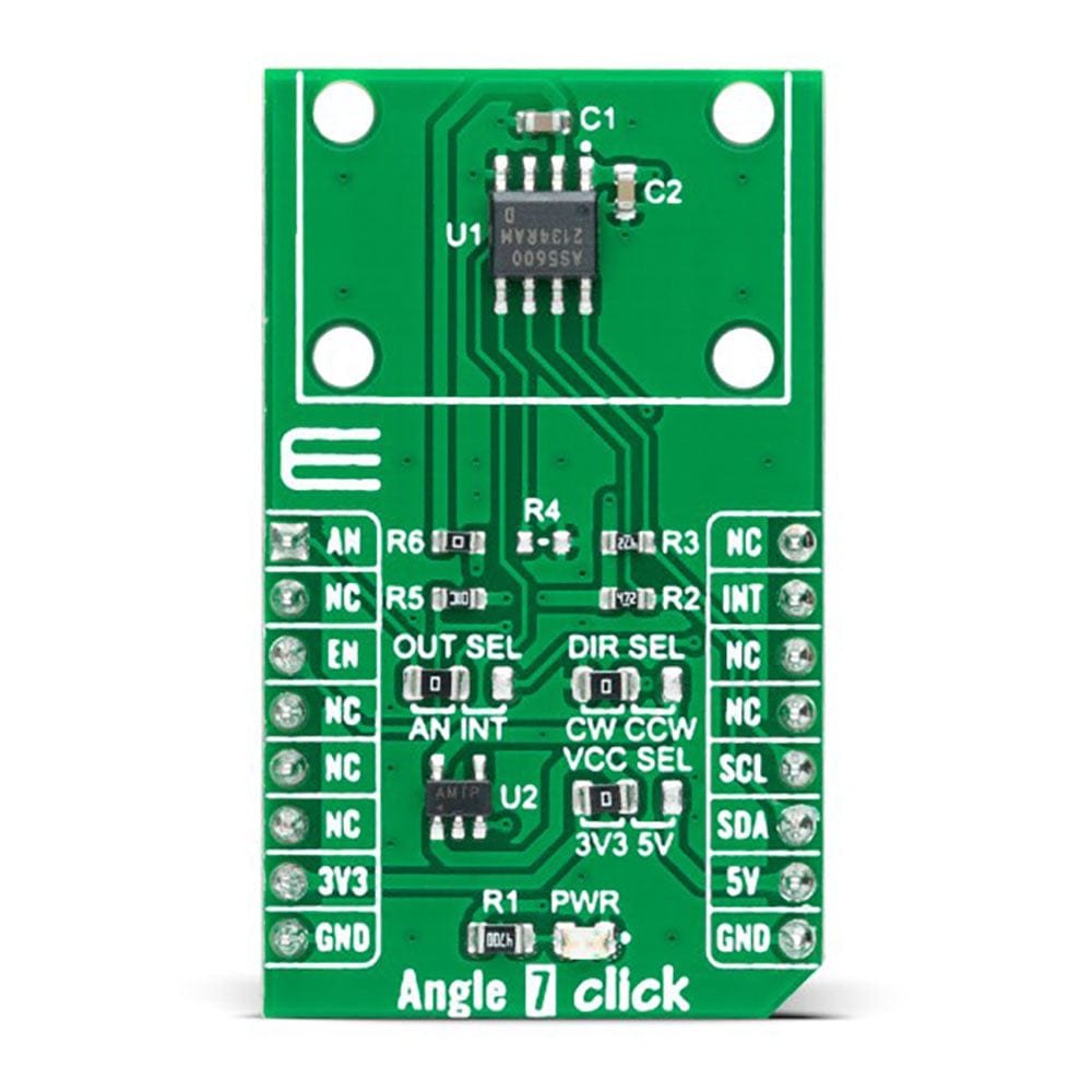
PINOUT DIAGRAM
This table shows how the pinout on the Angle 7 Click Board™ corresponds to the pinout on the mikroBUS™ socket (the latter shown in the two middle columns).
| Notes | Pin | Pin | Notes | ||||
|---|---|---|---|---|---|---|---|
| Analog Signal | AN | 1 | AN | PWM | 16 | NC | |
| NC | 2 | RST | INT | 15 | INT | PWM Signal | |
| NC | 3 | CS | RX | 14 | NC | ||
| NC | 4 | SCK | TX | 13 | NC | ||
| NC | 5 | MISO | SCL | 12 | SCL | I2C Clock | |
| NC | 6 | MOSI | SDA | 11 | SDA | I2C Data | |
| Power Supply | 3.3V | 7 | 3.3V | 5V | 10 | 5V | Power Supply |
| Ground | GND | 8 | GND | GND | 9 | GND | Ground |
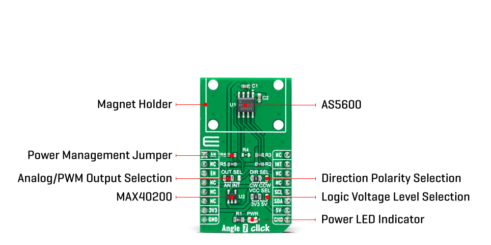
ONBOARD SETTINGS AND INDICATORS
| Label | Name | Default | Description |
|---|---|---|---|
| LD1 | PWR | - | Power LED Indicator |
| JP1 | VCC SEL | Left | Logic Level Voltage Selection 3V3/5V: Left position 3V3, Right position 5V |
| JP2 | OUT SEL | Left | Analog/PWM Output Selection AN/INT: Left position AN, Right position INT |
| JP3 | DIR SEL | Left | Direction Polarity Selection CW/CCW: Left position CW, Right position CCW |
| R6 | R6 | Populated | Power Management Jumper |
ANGLE 7 CLICK ELECTRICAL SPECIFICATIONS
| Description | Min | Typ | Max | Unit |
|---|---|---|---|---|
| Supply Voltage | 3.3 | - | 5 | V |
| Angle Measurement Range | 18 | - | 360 | deg |
| Resolution | - | 12 | - | bit |
| Operating Temperature Range | -40 | +25 | +120 | °C |
| General Information | |
|---|---|
Part Number (SKU) |
MIKROE-5196
|
Manufacturer |
|
| Physical and Mechanical | |
Weight |
0.02 kg
|
| Other | |
EAN |
8606027388279
|
Frequently Asked Questions
Have a Question?
Be the first to ask a question about this.