


Mikroelektronika d.o.o.
Magnetic Rotary 2 Click Board™
Magnetic Rotary 2 Click Board™
SKU: MIKROE-4952
Couldn't load pickup availability
Overview
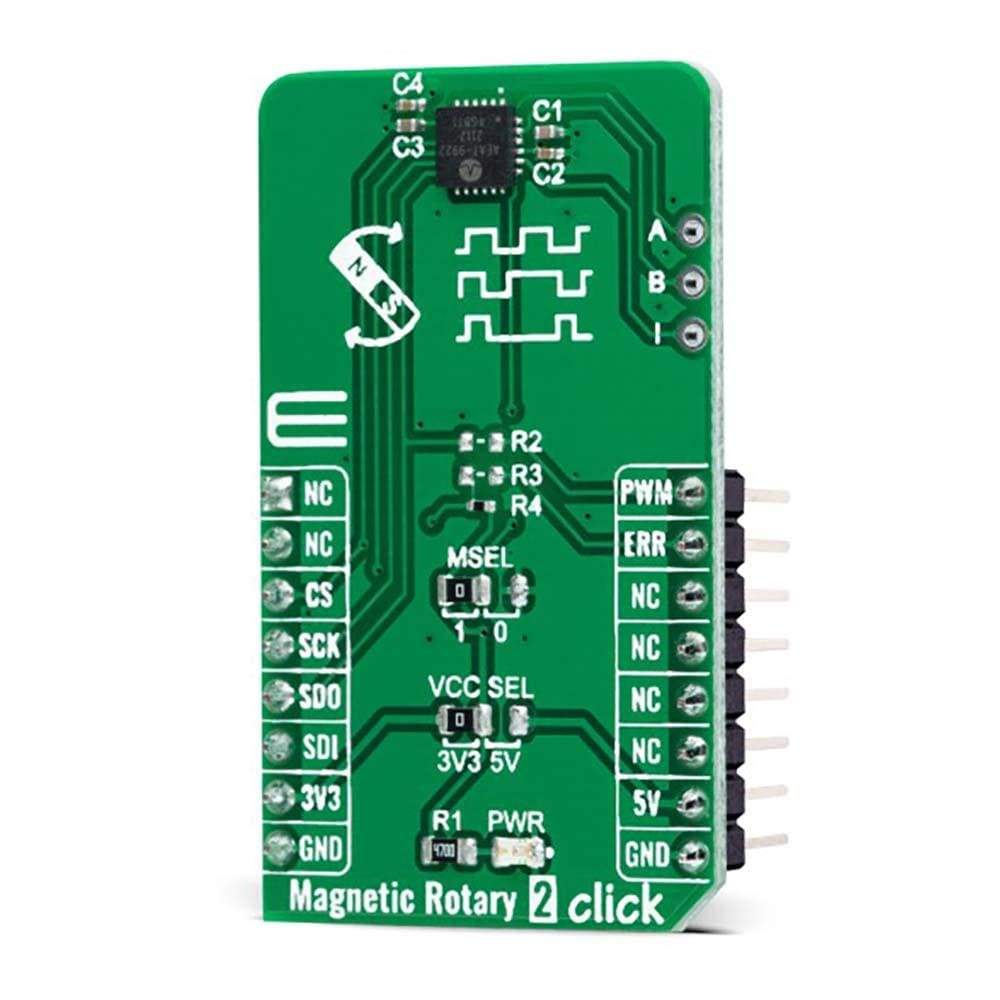
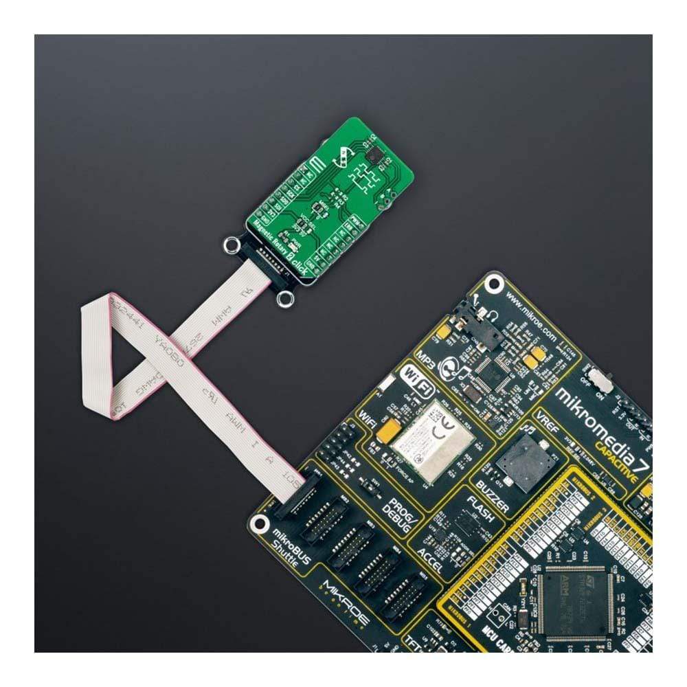
The Magnetic Rotary 2 Click Board™ is a compact add-on board used for accurate magnet-position sensing. This board features the AEAT-9922, an angular magnetic rotary sensor providing accurate angular measurement over a full 360 degrees of rotation from Broadcom Limited. The AEAT-9922 uses integrated Hall sensor elements with complex analogue and digital signal processing within a single device. The absolute angle measurement provides an instant indication of the magnet's angular position with a selectable and one-time programmable resolution from 10 to 18 bits. It also comes with an onboard header reserved for incremental outputs of their respective A, B, and I pins, the same as the commutation U, V, and W signals.
The Magnetic Rotary 2 Click Board™ represents a versatile solution capable of supporting a broad range of applications with its robust architecture to measure and deliver absolute and incremental signals.
Downloads
How Does The Magnetic Rotary 2 Click Board™ Work?
The Magnetic Rotary 2 Click Board™ as its foundation uses the AEAT-9922, an angular magnetic rotary sensor manufactured with a CMOS standard process providing accurate angular measurement over a full 360 degrees of rotation from Broadcom Limited. It can accurately measure a magnet's rotational angle when it is placed in alignment and perpendicular to the device by using its integrated Hall sensors to detect its magnetic field. The detected magnetic signals are then taken as input signals to be properly conditioned to negate their non-idealities before inputting them into the analog amplifiers for strength amplification and filtering. After which, the amplified analog signals are then fed into the internal analog-to-digital converter (ADC) to be converted into digital signals for the final digital processing stage.
A simple two-pole magnet generates the necessary magnetic field by rotating it perpendicularly. Wide magnetic field sensor configurations allow On-Axis (end of shaft) or Off-Axis (side of the shaft) modes in application. The used magnet should have sufficient magnetic field strength (mT) to generate the magnetic field for signal generation. The device provides digital information of magnetic field strength high and magnetic field strength low to indicate whether the magnets are too close or far away from our device's surface.
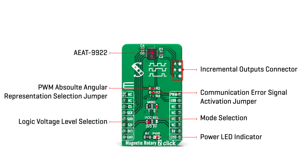
The Magnetic Rotary 2 Click Board™ communicates with MCU through a standard SPI interface supporting the common SPI mode, SPI Mode 1. Digital processing provides a digitized output of the absolute and incremental signals. Each output is configurable via CS pin, MSEL (Mode Selection for desirable protocol) jumper, and AEAT-9922 internal PSEL registers configurable through memory. In addition, an absolute angular representation also can be selected using a pulse width modulated (PWM) signal by populating onboard R2 resistor, which provides an instant indication of the magnet's angular position with a selectable and one-time programmable resolution from 10 to 18 bits. Alongside this feature, the communication error signal labelled as ERR and routed on the INT pin of the mikroBUS™ socket can be activated by populating the onboard R3 resistor.
The incremental outputs are available from digital outputs of their respective A, B, and I pins, the same for the U, V, and W commutation signals, routed to the upper-right side onboard header. The incremental positions are indicated on ABI and UVW signals with a comprehensive user-configurable resolution from 1CPR and up to 10,000CPR of ABI signals, and pole pairs from 1 to 32 pole pairs (from 2 to 64 poles) for UVW commutation signals.
The Magnetic Rotary 2 Click Board™ can operate with both 3.3V and 5V logic voltage levels selected via the VCC SEL jumper. This way, it is allowed for both 3.3V and 5V capable MCUs to use the communication lines properly. However, the Click board™ comes equipped with a library containing easy-to-use functions and an example code that can be used, as a reference, for further development.
SPECIFICATIONS
| Type | Magnetic |
| Applications | Can be used as a versatile solution capable of supporting a broad range of applications with its robust architecture to measure and deliver absolute and incremental signals |
| On-board modules | AEAT-9922 - an angular magnetic rotary sensor manufactured with a CMOS standard process providing accurate angular measurement over a full 360 degrees of rotation from Broadcom Limited |
| Key Features | Programmable angular magnetic encoder, selectable angular resolution, flexible incremental ABI resolution, user-programmable zero position, direction, index width and index position, SPI interface, and more |
| Interface | SPI |
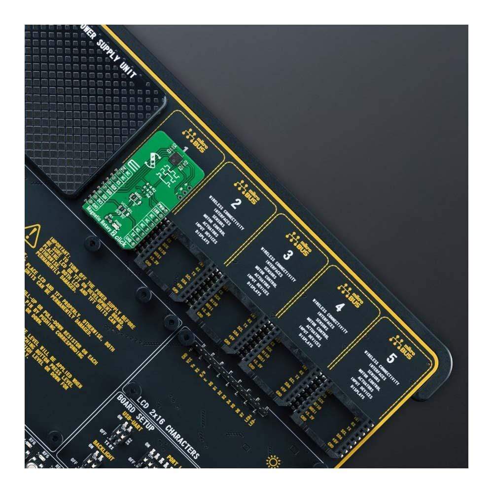
| Compatibility | mikroBUS |
| Click board size | M (42.9 x 25.4 mm) |
| Input Voltage | 3.3V or 5V |
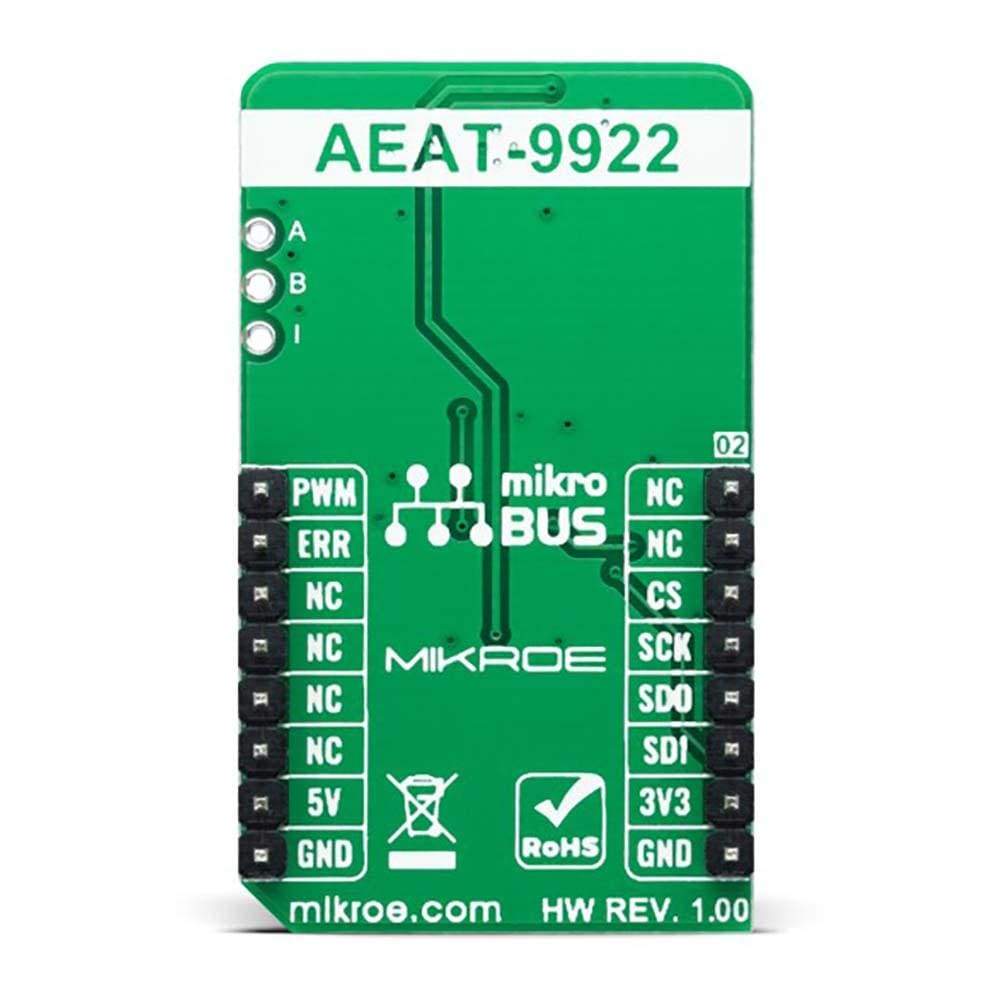
PINOUT DIAGRAM
This table shows how the pinout for the Magnetic Rotary 2 Click Board™ corresponds to the pinout on the mikroBUS™ socket (the latter shown in the two middle columns).
| Notes | Pin | Pin | Notes | ||||
|---|---|---|---|---|---|---|---|
| NC | 1 | AN | PWM | 16 | PWM | PWM Signal | |
| NC | 2 | RST | INT | 15 | ERR | Communication Error | |
| SPI Chip Select | CS | 3 | CS | RX | 14 | NC | |
| SPI Clock | SCK | 4 | SCK | TX | 13 | NC | |
| SPI Data OUT | SDO | 5 | MISO | SCL | 12 | NC | |
| SPI Data IN | SDI | 6 | MOSI | SDA | 11 | NC | |
| Power Supply | 3.3V | 7 | 3.3V | 5V | 10 | 5V | Power Supply |
| Ground | GND | 8 | GND | GND | 9 | GND | Ground |
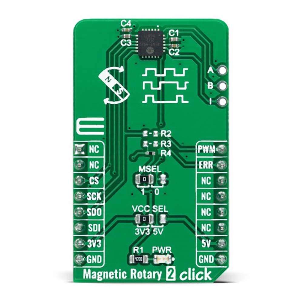
ONBOARD SETTINGS AND INDICATORS
| Label | Name | Default | Description |
|---|---|---|---|
| LD1 | PWR | - | Power LED Indicator |
| JP1 | VCC SEL | Left | Logic Level Voltage Selection 3V3/5V: Left position 3V3, Right position 5V |
| JP2 | MSEL | Left | Mode Selection 1/0: Left position 1, Right position 0 |
| J1 | ABI | Unpopulated | Incremental Outputs Header |
MAGNETIC ROTARY 2 CLICK ELECTRICAL SPECIFICATIONS
| Description | Min | Typ | Max | Unit |
|---|---|---|---|---|
| Supply Voltage | 3.3 | - | 5 | V |
| Magnet Rotation Angle Range | 0 | - | 360 | deg |
| Absolute Resolution | 10 | - | 18 | bits |
| Incremental Output Resolution (ABI) | 1 | - | 10.000 | CPR |
| Operating Temperature Range | -40 | +25 | +125 | °C |
| General Information | |
|---|---|
Part Number (SKU) |
MIKROE-4952
|
Manufacturer |
|
| Physical and Mechanical | |
Weight |
0.02 kg
|
| Other | |
EAN |
8606027389887
|
Frequently Asked Questions
Have a Question?
Be the first to ask a question about this.