


Mikroelektronika d.o.o.
SKU: MIKROE-4940Load Cell 6 Click Board
Load Cell 6 Click Board
Couldn't load pickup availability
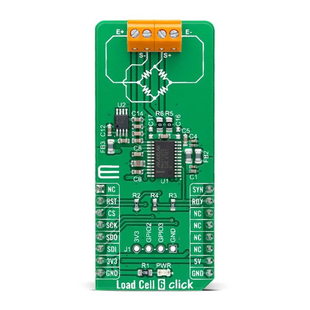
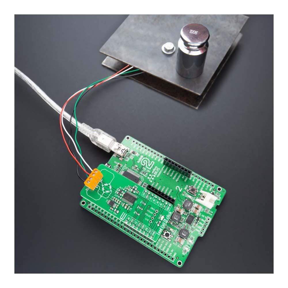
The Load Cell 6 Click Board™ is a compact add-on board representing a weigh scale solution. This board features the MAX11270, a high-performance 24-bit delta-sigma ADC that achieves excellent 130dB SNR while dissipating an ultra-low 10mW from Maxim Integrated, now part of Analog Devices. This SPI-configurable ADC sample rates up to 64ksps allow precision DC and AC measurements, with integral non-linearity guaranteed to 4ppm maximum. The MAX11270 offers a 6.5nV/√Hz noise programmable gain amplifier with gain settings between 1x to 128x. Optional buffers are also included to isolate the signal inputs from the switched capacitor sampling network, which allows the MAX11270 to be used with high-impedance sources without compromising the available dynamic range.
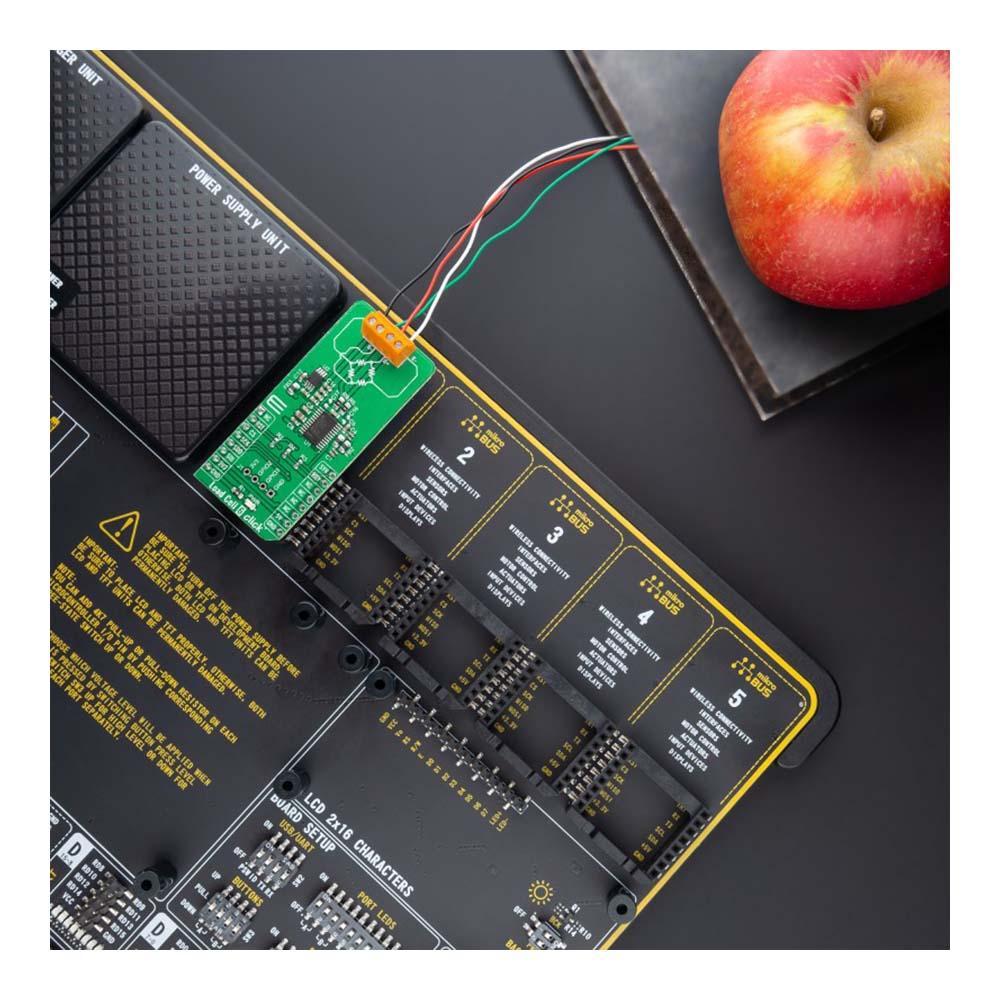
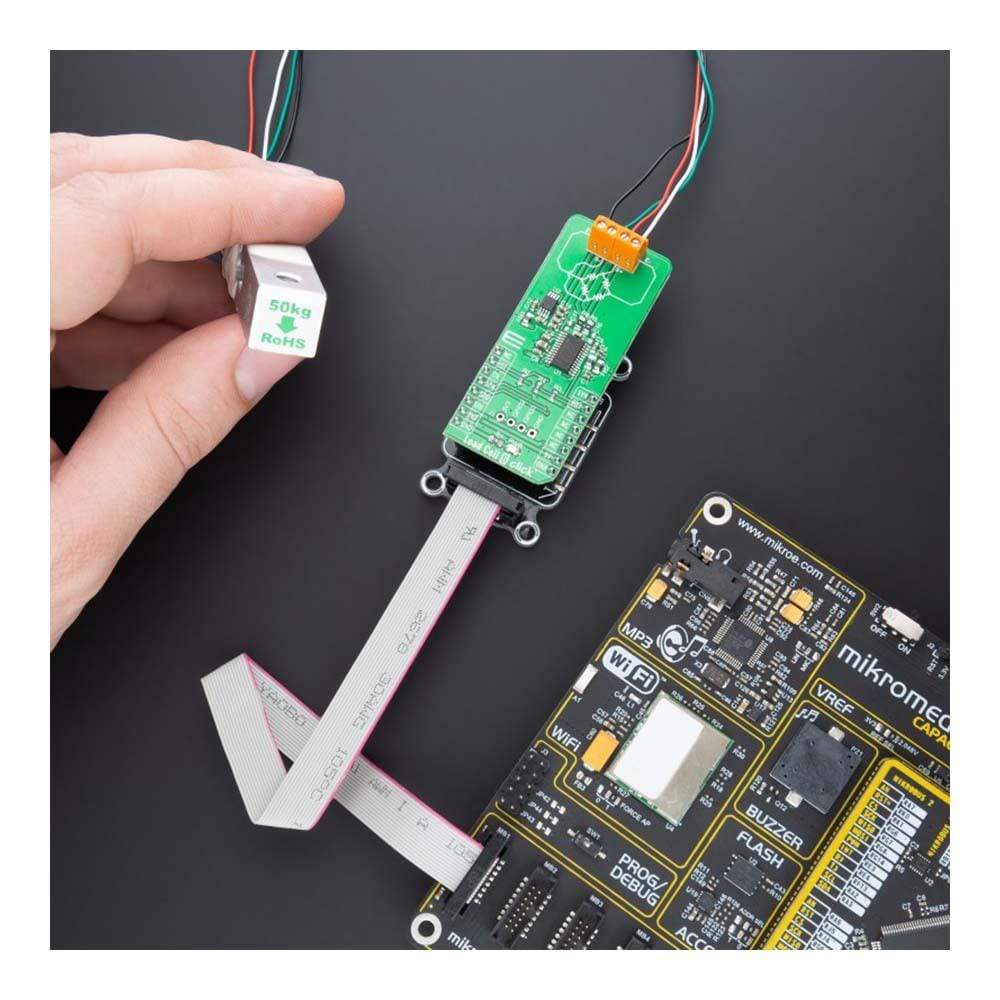
The Load Cell 6 Click Board™ is suitable for weight scale applications in various use cases.

How Does The Load Cell 6 Click Board™ Work?
The Load Cell 6 Click Board™ as its foundation uses the MAX11270, a pin programmable, ultra-low power 24-bit ΣΔ ADC that resolves a very high dynamic range from Maxim Integrated, now part of Analog Devices. The MAX11270 achieves excellent 130dB SNR while dissipating an ultra-low 10mW. It allows users to select a programmable gain amplifier with gain settings between 1x to 128x, unity-gain buffer, or connect signals directly to the delta-sigma sampling network. This ADC can resolve micro-volt level changes to the analogue input, making it a good fit for seismic, instrumentation, and ATE applications.
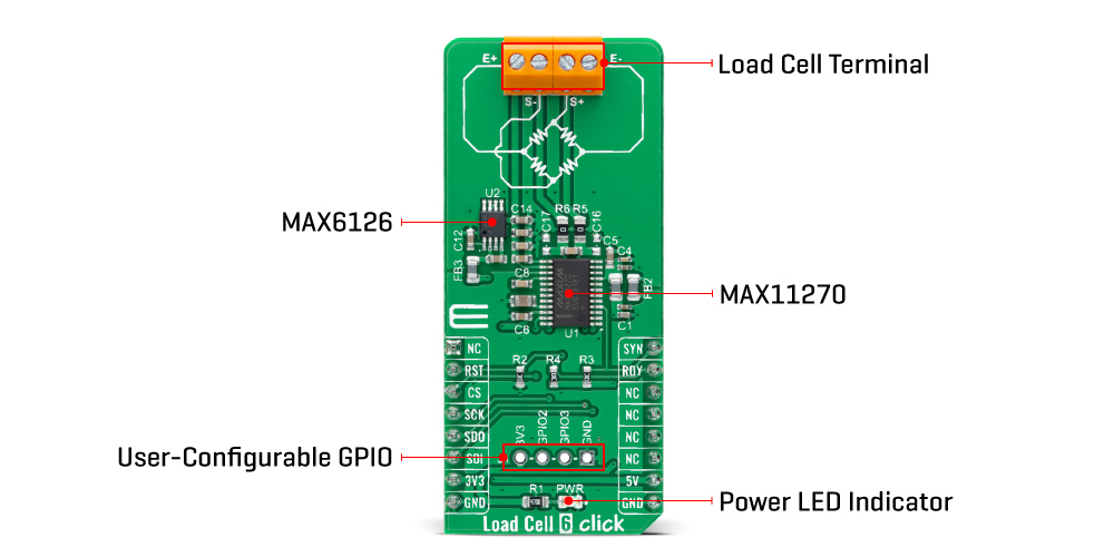
The MAX11270 measures a pair of differential analogue inputs (S+, S-) in buffered, direct connect, or PGA. The default configuration is directly connected, with PGA and input buffers powered down. These optional buffers isolate the signal inputs from the switched capacitor sampling network, which allows the MAX11270 to be used with high-impedance sources without compromising the available dynamic range. The ADC input range is programmable for unipolar (0 to VREF) ranges set by the reference voltage value obtained by the MAX6126, a 3V high-precision voltage reference, also routed to the E+ terminal.
The Load Cell 6 Click Board™ communicates with MCU through a standard SPI interface that enables high clock speeds up to 5MHz. The MAX11270 is highly configurable via the internal registers, accessed via the SPI interface. It operates in two modes: Conversion mode or Register-Access mode selected by the command byte. Those registers include PGA gain selection, offset and gain calibration, and a scalable sample rate to optimize performance. It also offers software-selectable output data rates, up to 12.8ksps with no data latency and 64ksps continuous, to optimize data rate and noise.
In addition, it uses the Reset pin, routed to the RST pin of the mikroBUS™ socket, is used for a complete reset of all digital functions resulting in a Power-On reset default state, while the Data-Ready signal, labelled as RDY and routed to the INT pin of the mikroBUS™ socket, notifies the host MCU when the data is ready. The Sync Reset signal is also used, labelled as SYN, and routed to the PWM pin of the mikroBUS™ socket, which resets both the digital filter and modulator. It also has a GPIO header with two general-purpose pins from the MAX11270 which are user-configurable.
Even though this board uses both mikroBUS™ power rails, this Click Board™ can only be operated with a 3.3V logic voltage level (5V is used only as a voltage reference power supply). The board must perform appropriate logic voltage level conversion before using MCUs with different logic levels. However, the Load Cell 6 Click Board™ equipped comes equipped with a library containing functions and an example code that can be used, as a reference, for further development.
SPECIFICATIONS
| Type | Force |
| Applications | Can be used for weight scale applications in various use cases |
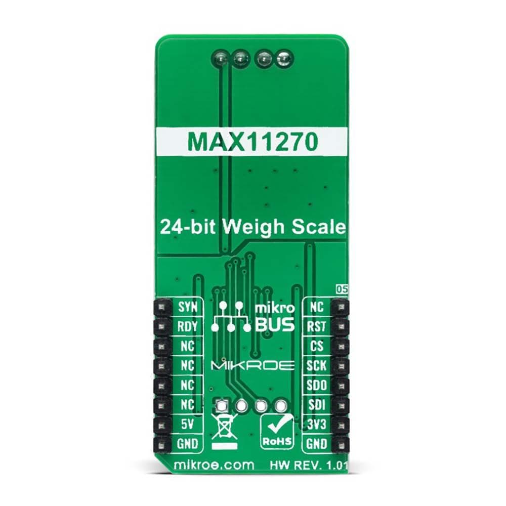
| On-board modules | MAX11270 - pin programmable, ultra-low power 24-bit ΣΔ ADC that resolves a very high dynamic range from Analog Devices |
| Key Features | High-resolution for instrumentation applications that require a wide dynamic range, high accuracy for DC measurements, flexible high-performance filter architecture, and more |
| Interface | SPI |
| Compatibility | mikroBUS |
| Click Board™ board size | L (57.15 x 25.4 mm) |
| Input Voltage | 3.3V,5V |
PINOUT DIAGRAM
This table shows how the pinout on the Load Cell 6 Click Board™ corresponds to the pinout on the mikroBUS™ socket (the latter shown in the two middle columns).
| Notes | Pin | Pin | Notes | ||||
|---|---|---|---|---|---|---|---|
| NC | 1 | AN | PWM | 16 | SYN | Sync Reset | |
| Reset | RST | 2 | RST | INT | 15 | RDY | Data-Ready |
| SPI Chip Select | CS | 3 | CS | RX | 14 | NC | |
| SPI Clock | SCK | 4 | SCK | TX | 13 | NC | |
| SPI Data OUT | SDO | 5 | MISO | SCL | 12 | NC | |
| SPI Data IN | SDI | 6 | MOSI | SDA | 11 | NC | |
| Power Supply | 3.3V | 7 | 3.3V | 5V | 10 | 5V | Power Supply |
| Ground | GND | 8 | GND | GND | 9 | GND | Ground |
ONBOARD SETTINGS AND INDICATORS
| Label | Name | Default | Description |
|---|---|---|---|
| LD1 | PWR | - | Power LED Indicator |
| J1 | GPIO | Unpopulated | User-Configurable GPIO Header |
LOAD CELL 6 CLICK ELECTRICAL SPECIFICATIONS
| Description | Min | Typ | Max | Unit |
|---|---|---|---|---|
| Supply Voltage | - | 3.3 | - | V |
| Analog Input Voltage Range | 0 | - | 3 | V |
| Resolution | - | 24 | - | bit |
| Operating Temperature Range | -40 | +25 | +85 | °C |
Software Support
We provide a library for the Load Cell 6 Click Board™ as well as a demo application (example), developed using MikroElektronika compilers. The demo can run on all the main MikroElektronika development boards.
The package can be downloaded/installed directly from NECTO Studio The package Manager (recommended), downloaded from our LibStock™ or found on Mikroe Github account.
Library Description
This library contains API for the Load Cell 6 Click Board™ driver.
Key functions
loadcell6_get_weightLoad Cell 6 get weight function.
loadcell6_calibrationLoad Cell 6 calibration function.
loadcell6_tareLoad Cell 6 tare the scales function.
Example Description
This library contains API for the Load Cell 6 Click Board™ driver. The library initializes and defines the SPI bus drivers to read status and ADC data. The library also includes a function for tare, calibration and weight measurement.
void application_task ( void )
{
    static float weight_g;

    if ( LOADCELL6_OK == loadcell6_get_weight( &loadcell6, &cell_data, &weight_g ) )
    {
        log_printf(&logger, "   Weight : %.2f grn", weight_g );
    }
}
The full application code, and ready to use projects can be installed directly from NECTO Studio The Package Manager (recommended), downloaded from our LibStock™ or found on Mikroe Github account.
Other Mikroe Libraries used in the example:
- MikroSDK.Board
- MikroSDK.Log
- Click Board™.Barometer7
Additional Notes and Information
Depending on the development board you are using, you may need a USB UART Click Board™, USB UART 2 Click Board™ or RS232 Click Board™ to connect to your PC, for development systems with no UART to USB interface available on the board. UART terminal is available in all MikroElektronika compilers.
MIKROSDK
The Load Cell 6 Click Board™is supported with mikroSDK - MikroElektronika Software Development Kit. To ensure proper operation of mikroSDK compliant Click Board™ board™ demo applications, mikroSDK should be downloaded from the LibStock and installed for the compiler you are using.
Load Cell 6 Click Board
Frequently Asked Questions
Have a Question?
Be the first to ask a question about this.