

Mikroelektronika d.o.o.
ADC 16 Click Board™
ADC 16 Click Board™
SKU: MIKROE-4937
Couldn't load pickup availability


Key Features
Overview
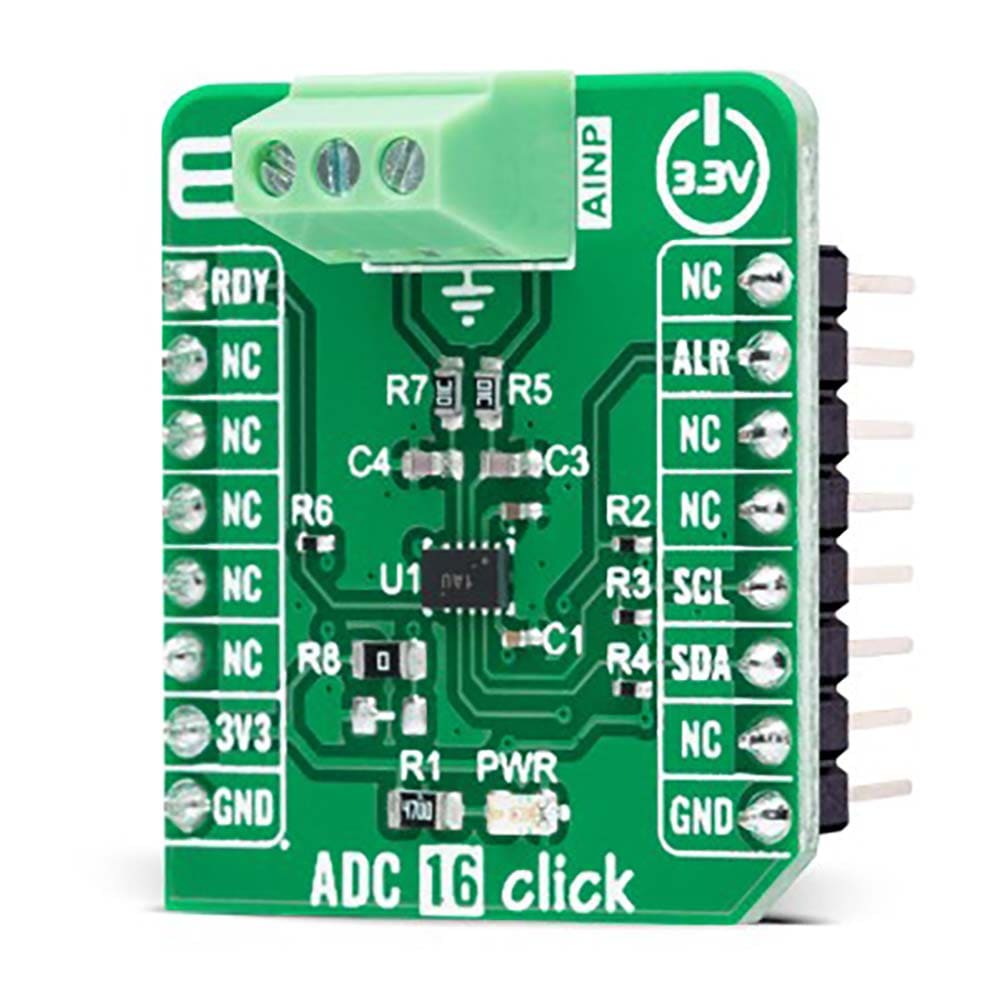
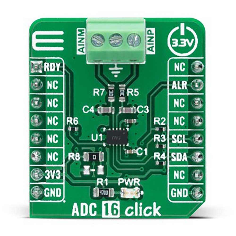
The ADC 16 Click Board™ is a compact add-on board that contains a high-performance data converter. This board features the ADS7142-Q1, a low-power two-channel 12-bit analog-to-digital converter from Texas Instruments. This I2C configurable 140kSPS successive approximation register (SAR) analog-to-digital converter (ADC) can autonomously monitor signals while maximizing system power, reliability, and performance. It implements event-triggered interrupts per channel using a digital window comparator with programmable high and low thresholds, hysteresis, and event counter. This Click board™ offers high accuracy solution for the most demanding applications, from general-purpose monitoring applications (voltage, current, and temperature) to portable consumer electronics and more.
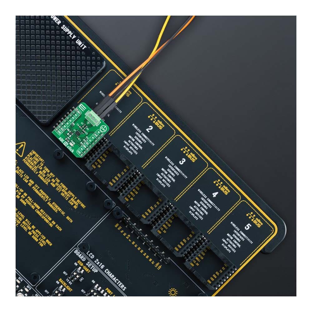
The ADC 16 Click Board™ is supported by a mikroSDK compliant library, which includes functions that simplify software development. This Click board™ comes as a fully tested product, ready to be used on a system equipped with the mikroBUS™ socket.
Downloads
How Does The ADC 16 Click Board™ Work?
The ADC 16 Click Board™ is based on the ADS7142-Q1, a high-performance two-channel analog-to-digital converter (ADC) from Analog Devices. The ADS7142-Q1 represents a dual-channel, 12-bit programmable sensor monitor with an integrated 140kSPS SAR-ADC, input multiplexer, digital comparator, data buffer, accumulator, and internal oscillator. The input multiplexer can be configured as two single-ended channels, one single-ended channel with remote ground sensing, or one pseudo-differential channel where the input can swing to approximately half the value of its analog supply input.
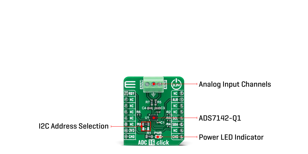
The ADC 16 Click Board™ communicates with MCU using the standard I2C 2-Wire interface to read data and configure settings. Besides, the ADS7142-Q1 allows choosing the least significant bit (LSB) of its I2C slave address using the SMD resistors labelled R8 and R9. This Click board™ also implements event-triggered interrupts per channel, labelled as RDY and ALR and routed on the AN and INT pins of the mikroBUS™ socket, using a digital window comparator with programmable high and low thresholds, hysteresis, and event counter.
The ADC 16 Click Board™ can be operated only with a 3.3V logic voltage level. The board must perform appropriate logic voltage level conversion before using MCUs with different logic levels. However, the Click board™ comes equipped with a library containing functions and an example code that can be used, as a reference, for further development.
SPECIFICATIONS
| Type | ADC |
| Applications | The ADC 16 Click Board™ can be used from general-purpose monitoring applications (voltage, current, and temperature) to portable consumer electronics and more |
| On-board modules | ADS7142-Q1 - high-performance two-channel analog-to-digital converter (ADC) from Analog Devices |
| Key Features | Two single-ended channels/One single-ended channel with remote ground sensing/One pseudo-differential channel, low power consumption, 12-bit noise-free resolution, 140kSPS sampling rate, efficient host sleep and wake-up feature, false trigger prevention, and more |
| Interface | I2C |
| Compatibility | mikroBUS |
| Click board size | S (28.6 x 25.4 mm) |
| Input Voltage | 3.3V |
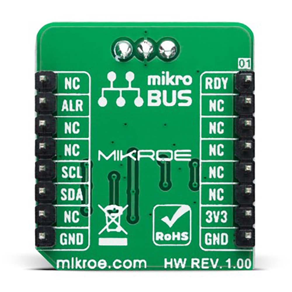
PINOUT DIAGRAM
This table shows how the pinout on ADC 16 Click corresponds to the pinout on the mikroBUS™ socket (the latter shown in the two middle columns).
| Notes | Pin | Pin | Notes | ||||
|---|---|---|---|---|---|---|---|
| Data Ready Interrupt | RDY | 1 | AN | PWM | 16 | NC | |
| NC | 2 | RST | INT | 15 | ALR | Event Alert Interrupt | |
| NC | 3 | CS | RX | 14 | NC | ||
| NC | 4 | SCK | TX | 13 | NC | ||
| NC | 5 | MISO | SCL | 12 | SCL | I2C Clock | |
| NC | 6 | MOSI | SDA | 11 | SDA | I2C Data | |
| Power Supply | 3.3V | 7 | 3.3V | 5V | 10 | NC | |
| Ground | GND | 8 | GND | GND | 9 | GND | Ground |
ONBOARD SETTINGS AND INDICATORS
| Label | Name | Default | Description |
|---|---|---|---|
| LD1 | PWR | - | Power LED Indicator |
| R8 | R8 | Populated | I2C Address Selection Resistor |
| R9 | R9 | Unpopulated | I2C Address Selection Resistor |
ADC 16 CLICK ELECTRICAL SPECIFICATIONS
| Description | Min | Typ | Max | Unit |
|---|---|---|---|---|
| Supply Voltage | - | 3.3 | - | V |
| Analog Input Voltage | 0 | - | 3.3 | V |
| Resolution | - | 12 | - | bits |
| Operating Temperature Range | -40 | +25 | +120 | °C |
Software Support
We provide a library for the ADC 16 Click Board™ as well as a demo application (example), developed using MikroElektronika compilers. The demo can run on all the main MikroElektronika development boards.
The package can be downloaded/installed directly from NECTO Studio The package Manager (recommended), downloaded from our LibStock™ or found on MikroE Github account.
Library Description
This library contains API for the ADC 16 Click Board™ driver.
Key functions
-
adc16_single_register_writeThis function writes a single data to the selected register. -
adc16_single_register_readThis function reads a single data from the selected register. -
adc16_get_voltageThis function reads the voltage from two analog input single-ended channels.
Example Description
This example demonstrates the use of the ADC 16 Click Board™ by reading the voltage from the two analog input channels.
void application_task ( void )
 {
     float ain0_voltage, ain1_voltage;
     if ( ADC16_OK == adc16_get_voltage ( &adc16, &ain0_voltage, &ain1_voltage ) )
     {
         log_printf ( &logger, " AIN0 voltage: %.3f V rn", ain0_voltage );
         log_printf ( &logger, " AIN1 voltage: %.3f V rnn", ain1_voltage );
         Delay_ms ( 100 );
     }
 }
The full application code, and ready to use projects can be installed directly from NECTO Studio The package Manager (recommended), downloaded from our LibStock™ or found on MikroE Github account.
Other MikroE Libraries used in the example:
- MikroSDK.Board
- MikroSDK.Log
- Click.ADC16
Additional Notes and Information
Depending on the development board you are using, you may need USB UART click, USB UART 2 Click or RS232 Click to connect to your PC, for development systems with no UART to USB interface available on the board. UART terminal is available in all MikroElektronika compilers.
MIKROSDK
The ADC 16 Click Board™ is supported with mikroSDK - MikroElektronika Software Development Kit. To ensure proper operation of mikroSDK compliant Click board™ demo applications, mikroSDK should be downloaded from the LibStock and installed for the compiler you are using.
| General Information | |
|---|---|
Part Number (SKU) |
MIKROE-4937
|
Manufacturer |
|
| Physical and Mechanical | |
Weight |
0.02 kg
|
| Other | |
EAN |
8606027389375
|
Frequently Asked Questions
Have a Question?
Be the first to ask a question about this.