


Mikroelektronika d.o.o.
DC Motor 21 Click Board™
DC Motor 21 Click Board™
SKU: MIKROE-4877
Couldn't load pickup availability
Overview
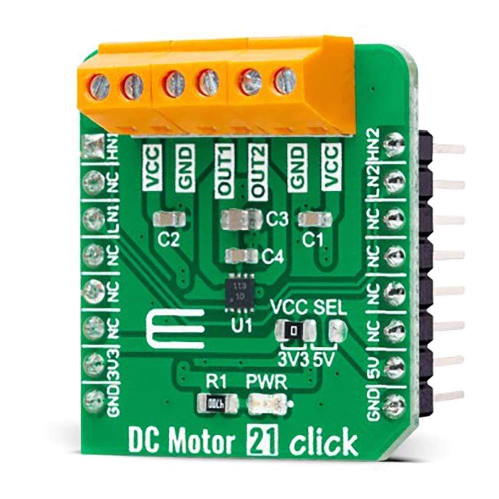
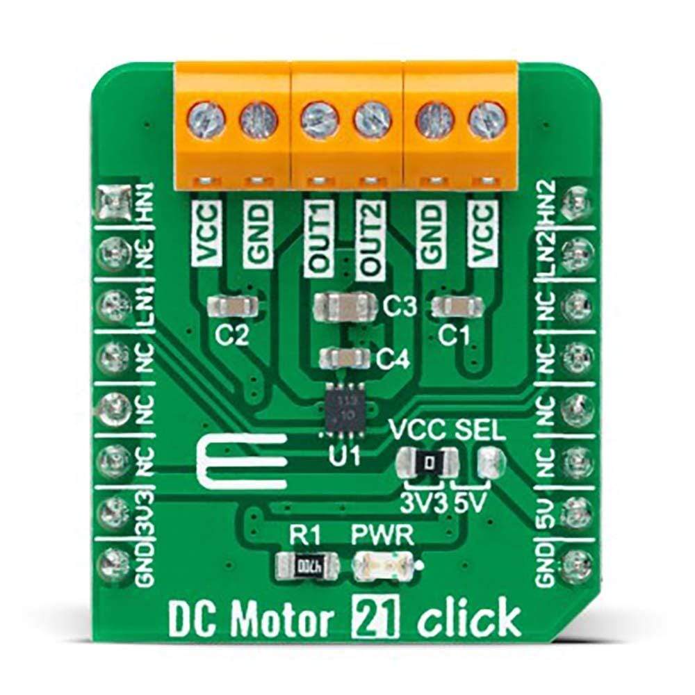
The DC Motor 21 Click Board™ is a compact add-on board that contains a brushed DC motor driver. This board features the A3910, a DC motor driver designed for low voltage power applications from Allegro Microsystems. It is controlled via several GPIO pins and has a wide operating voltage range with an output current capacity of 500mA. In addition to the possibility to be used in the full-bridge configuration to drive a single bidirectional DC motor, it can also be used as a dual half-bridge to drive dual DC motors. Using an integrated MOS switch improves braking action for the motor, compared to implementation with a simple clamp diode. Besides, it also features built-in protection such as crossover current protection and thermal shutdown.
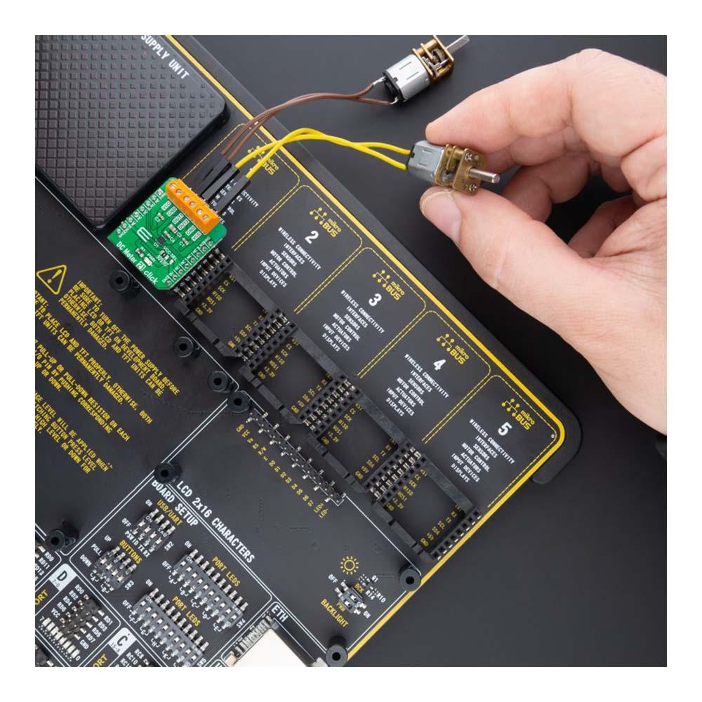
The DC Motor 21 Click Board™ is suitable for driving DC brushed motors and targeted at the consumer and industrial market with end applications to low voltage equipment.
Downloads
How Does The DC Motor 21 Click Board™ Work?
The DC Motor 21 Click Board™ is based on the A3910, a dual half-bridge motor driver designed for low voltage power applications from Allegro Microsystems. The DC Motor 21 Click Board™ is controlled via several GPIO pins of the mikroBUS™ socket and has a wide operating voltage range with an output current capacity of 500mA maximum. The integrated MOSFETs, which configures a half-bridge circuit inside the A3910, provide the possibility to drive dual DC motors but also allow to be used in the full-bridge configuration to drive a single bidirectional DC motor. Thanks to its plane features and benefits, the DC Motor 21 Click Board™ is targeted at the consumer market with end applications to low voltage equipment.
Using an integrated MOS switch improves braking action for the motor, compared to implementation with a simple clamp diode. Besides, it also features built-in protection such as crossover current and thermal shutdown protection, alongside "Sleep" Standby mode with zero drain-current.
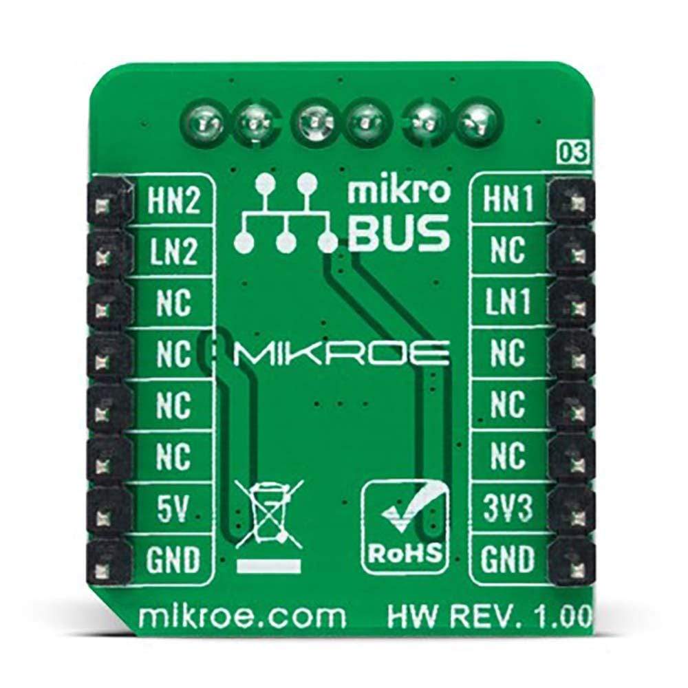
As mentioned in the product description, the DC Motor 21 Click Board™ communicates with MCU using several GPIO pins. To turn ON the internal MOSFETs of the A3910, they need to be switched by the logic level, which is input to the control input pins: HN1, LN1, HN2, and LN2 pins routed to the AN, CS, PWM, and INT pins of the mikroBUS™ socket. Thereby, the Drive/Break/Coast/Sleep motor functions can be selected according to the state of its input control signals.
The DC Motor 21 Click Board™ can operate with both 3.3V and 5V logic voltage levels selected via the VCC SEL jumper. This way, it is allowed for both 3.3V and 5V capable MCUs to use communication lines properly. However, the Click board™ comes equipped with a library containing easy-to-use functions and an example code that can be used, as a reference, for further development.
SPECIFICATIONS
| Type | Brushed |
| Applications | Can be used for driving DC brushed motors and targeted at the consumer and industrial market with end applications to low voltage equipment |
| On-board modules | A3910 - dual half-bridge motor driver designed for low voltage power applications from Allegro Microsystems |
| Key Features | Low power consumption, full- and half-bridge configuration, low rds, Standby mode with zero drain-current, crossover and thermal shutdown protection, and more |
| Interface | GPIO |
| Compatibility | mikroBUS |
| Click board size | S (28.6 x 25.4 mm) |
| Input Voltage | 3.3V or 5V |
PINOUT DIAGRAM
This table shows how the pinout on the DC Motor 21 Click Board™ corresponds to the pinout on the mikroBUS™ socket (the latter shown in the two middle columns).
| Notes | Pin | Pin | Notes | ||||
|---|---|---|---|---|---|---|---|
| Motor 1 Control Input | HN1 | 1 | AN | PWM | 16 | HN2 | Motor 2 Control Input |
| NC | 2 | RST | INT | 15 | LN2 | Motor 2 Control Input | |
| Motor 1 Control Input | LN1 | 3 | CS | RX | 14 | NC | |
| NC | 4 | SCK | TX | 13 | NC | ||
| NC | 5 | MISO | SCL | 12 | NC | ||
| NC | 6 | MOSI | SDA | 11 | NC | ||
| Power Supply | 3.3V | 7 | 3.3V | 5V | 10 | 5V | Power Supply |
| Ground | GND | 8 | GND | GND | 9 | GND | Ground |
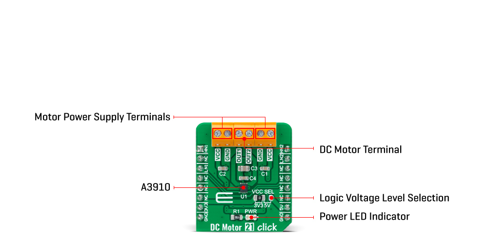
ONBOARD SETTINGS AND INDICATORS
| Label | Name | Default | Description |
|---|---|---|---|
| LD1 | PWR | - | Power LED Indicator |
| JP1 | VCC SEL | Left | Logic Level Voltage Selection 3V3/5V: Left position 3V3, Right position 5V |
DC MOTOR 21 CLICK ELECTRICAL SPECIFICATIONS
| Description | Min | Typ | Max | Unit |
|---|---|---|---|---|
| Supply Voltage | 3.3 | - | 5 | V |
| Maximum Output Current | - | - | 500 | mA |
| Operating Temperature Range | -40 | +25 | +85 | °C |
| General Information | |
|---|---|
Part Number (SKU) |
MIKROE-4877
|
Manufacturer |
|
| Physical and Mechanical | |
Weight |
0.02 kg
|
| Other | |
EAN |
8606027384219
|
Frequently Asked Questions
Have a Question?
Be the first to ask a question about this.