Overview
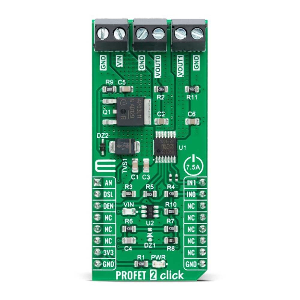
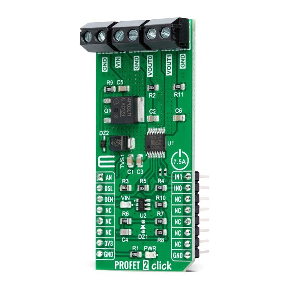
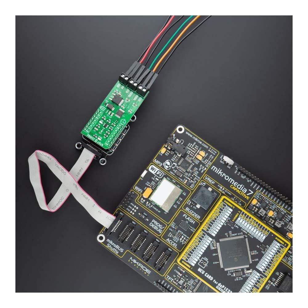
The PROFET™ 2 -7.5A Click Board™ is a compact add-on board that contains a smart high-side power switch. This board features the Profet™ BTS70082EPAXUMA1, a dual-channel, high-side power switch with embedded protection and diagnosis feature from Infineon Technologies. This switch has a driving capability suitable for 7.5A loads and high inrush current loads and features a ReverSave™, which causes the power transistor to switch on in case of reverse polarity. Besides its protection features, it also has several pin-configurable diagnosis features such as proportional load current sense, open Load in ON and OFF state, and short circuit to ground and battery.
The PROFET™ 2 -7.5A Click Board™ is suitable for resistive, inductive, and capacitive loads, replaces electromechanical relays, fuses and discrete circuits, and many more.
Downloads
How Does The PROFET™ 2-7A Click Board™ Work?
The PROFET™ 2-7A Click Board™ as its foundation uses the Profet™ BTS70082EPAXUMA1, a dual-channel, smart high-side power switch with embedded protection and diagnosis feature from Infineon Technologies. The BTS70082EPAXUMA1 has a driving capability suitable for 7.5A loads and comes equipped with "ReverseON" functionality which causes the power transistor to switch on in case of reverse polarity. It also offers outstanding energy efficiency with reduced current consumption, state-of-art current sense accuracy, and faster switching/slew rate with no impact on EMC, making it suitable for resistive, inductive, and capacitive loads, replacement of electromechanical relays, fuses, and discrete circuits, and many more.
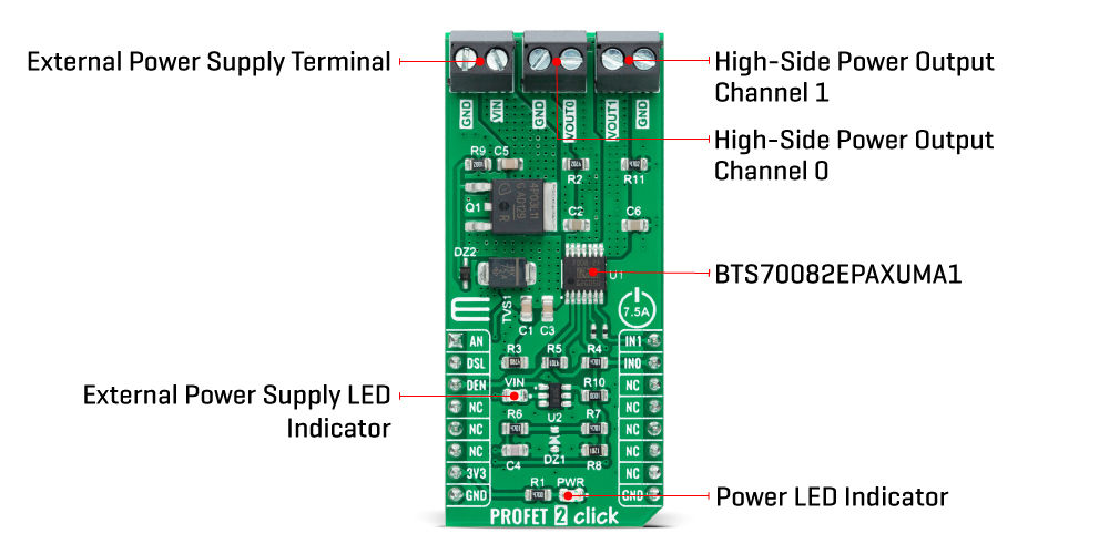
The PROFET™ 2-7A Click Board™ uses five digital pins for direct control. The input pins IN0 and IN1, routed to the PWM and INT pins of the mikroBUS™ socket, activate the corresponding output channels labelled VOUT0 and VOUT1. Also, the Diagnosis Enable (DEN) pin routed to the CS pin of the mikroBUS™ socket controls the diagnosis and protection circuitry, and in combination with IN pins, it enables the selection of appropriate operating states: Sleep, Stand-by, and Active Mode.
The BTS70082EPAXUMA1 is protected against overtemperature, overload, reverse power supply(GND and VIN are reverse supplied), and overvoltage. Overtemperature and overload protection work when the device is not in Sleep mode, while overvoltage protection works in all operation modes. For diagnosis purposes, the BTS70082EPAXUMA1 provides a combination of digital and analogue signals at the AN pin of the mikroBUS™ socket. Besides, the Diagnosis Selection DSEL pin, routed to the RST pin of the mikroBUS™ socket, selects the channel on which a diagnosis will be performed.
The PROFET™ 2 -7A Click Board™ supports an external power supply for the BTS70082EPAXUMA1, which can be connected to the input terminal labelled as VIN and should be within the range of 4.1V to 28V. VIN has an under-voltage detection circuit, which prevents the activation of the power output stages and diagnosis if the applied voltage is below the under-voltage threshold. A power supply indication, red LED labelled as VIN, indicates the presence of an external power supply.
This Click board™ can be operated only with a 3.3V logic voltage level. The board must perform appropriate logic voltage level conversion before use with MCUs with different logic levels. However, the Click board™ comes equipped with a library containing functions and an example code that can be used, as a reference, for further development.
SPECIFICATIONS
| Type | Power Switch |
| Applications | Can be used for resistive, inductive, and capacitive loads, replaces electromechanical relays, fuses and discrete circuits, and many more |
| On-board modules | BTS70082EPAXUMA1 - dual-channel, smart high-side power switch with embedded protection and diagnosis feature from Infineon Technologies |
| Key Features | High-side switch with diagnosis and embedded protection, reverseON for low power dissipation in reverse polarity, UVLO/OVLO, wide external power supply range with LED indication, and more |
| Interface | Analog,GPIO |
| Compatibility | mikroBUS |
| Click board size | L (57.15 x 25.4 mm) |
| Input Voltage | 3.3V,External |
PINOUT DIAGRAM
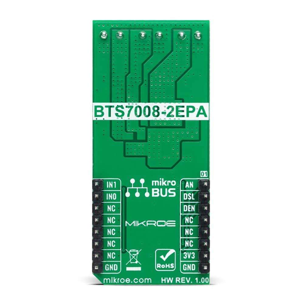
This table shows how the pinout on the PROFET™ 2-7A Click Board™ - 7A corresponds to the pinout on the mikroBUS™ socket (the latter shown in the two middle columns).
| Notes | Pin |  |
Pin | Notes | |||
|---|---|---|---|---|---|---|---|
| Diagnosis Signal | AN | 1 | AN | PWM | 16 | IN1 | Output Channel 1 Activation |
| Diagnosis Selection | DSL | 2 | RST | INT | 15 | IN0 | Output Channel 0 Activation |
| Diagnosis Enable | DEN | 3 | CS | RX | 14 | NC | |
| NC | 4 | SCK | TX | 13 | NC | ||
| NC | 5 | MISO | SCL | 12 | NC | ||
| NC | 6 | MOSI | SDA | 11 | NC | ||
| Power Supply | 3.3V | 7 | 3.3V | 5V | 10 | NC | |
| Ground | GND | 8 | GND | GND | 9 | GND | Ground |
ONBOARD SETTINGS AND INDICATORS
| Label | Name | Default | Description |
|---|---|---|---|
| LD1 | PWR | - | Power LED Indicator |
| LD2 | VIN | - | External Power Supply LED Indicator |
PROFET™ 2 CLICK - 7A ELECTRICAL SPECIFICATIONS
| Description | Min | Typ | Max | Unit |
|---|---|---|---|---|
| Supply Voltage VCC | - | 3.3 | - | V |
| External Supply Voltage VIN | 4.1 | - | 28 | V |
| Output Current | - | - | 7.5 | A |
| ON Resistance | - | - | 18 | mΩ |
| Operating Temperature Range | -40 | +25 | +150 | °C |
| General Information | |
|---|---|
Part Number (SKU) |
MIKROE-4819
|
Manufacturer |
|
| Physical and Mechanical | |
Weight |
0.02 kg
|
| Other | |
Country of Origin |
|
HS Code Customs Tariff code
|
|
EAN |
8606027384028
|
Warranty |
|
Frequently Asked Questions
Have a Question?
Be the first to ask a question about this.

