


Mikroelektronika d.o.o.
Analog MUX 4 Click Board™
Analog MUX 4 Click Board™
SKU: MIKROE-4795
Couldn't load pickup availability


Key Features
Overview
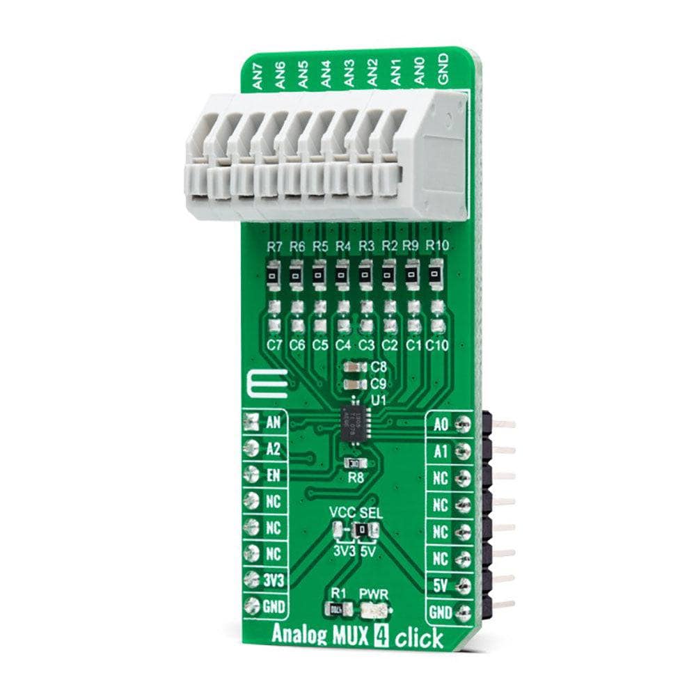
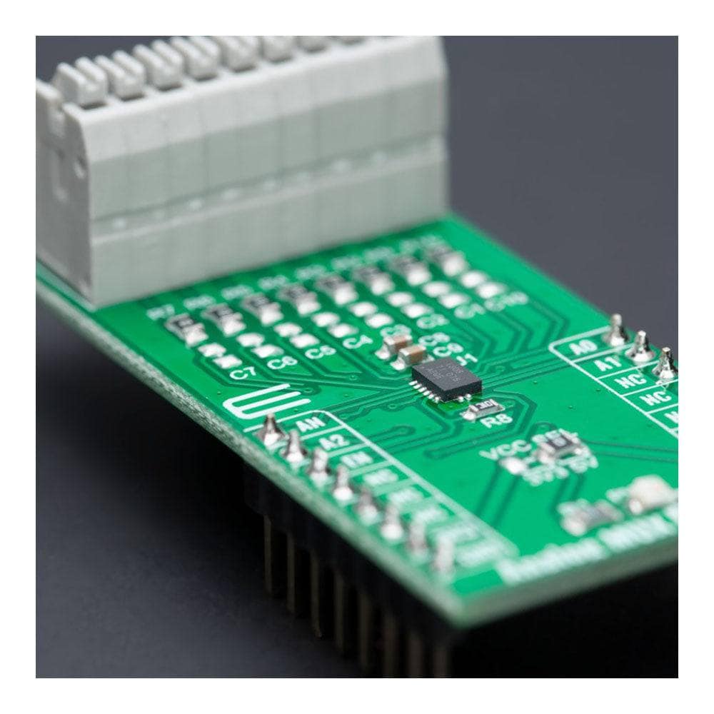
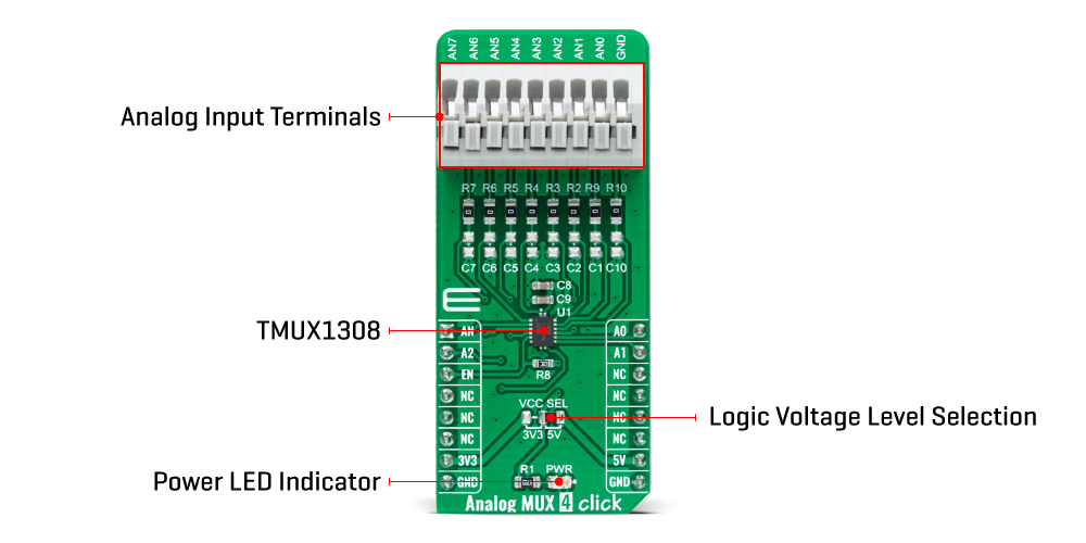
The Analog MUX 4 Click Board™ is a compact add-on board that switches one of eight analogue inputs to a single analogue output. This board features the TMUX1308, a general-purpose 8:1 single-ended CMOS multiplexer (MUX) from Texas Instruments. The TMUX1308 has an internal injection current control which eliminates the need for external diode and resistor networks to protect the switch and keep the input signals within the supply voltage. It also supports bidirectional analogue and digital signals ranging from 0 to 5V, alongside several protection features allowing a reliable operation and protecting the device from potential damage. This Click Board™ is suitable for various applications, from industrial to instrumentation, consumer, communications, and more.
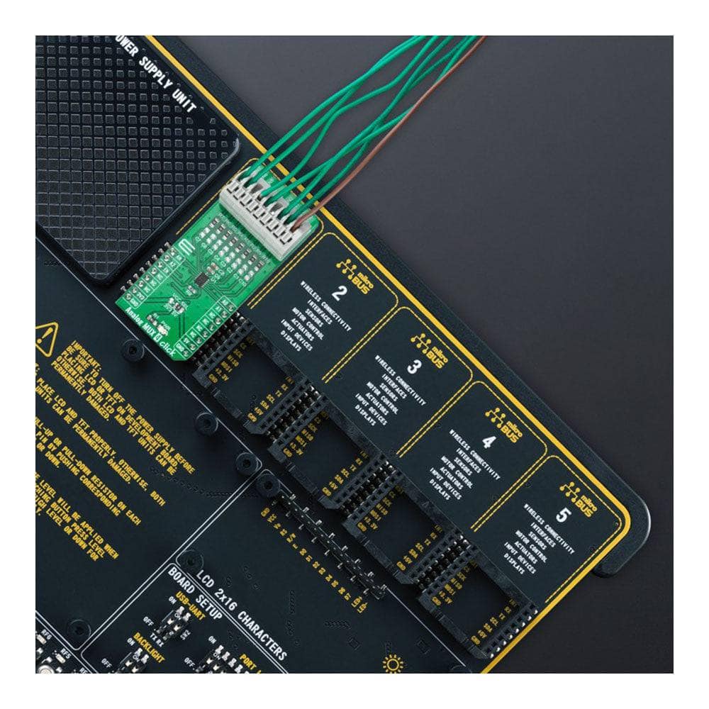
The Analog MUX 4 Click Board™ is supported by a mikroSDK compliant library, which includes functions that simplify software development. This Click board™ comes as a thoroughly tested product, ready to be used on a system equipped with the mikroBUS™ socket.
Downloads
How Does The Analog MUX 4 Click Board™ Work?
The Analog MUX 4 Click Board™ is based on the TMUX1308, a general-purpose 8:1 single-ended CMOS analogue multiplexer from Texas Instruments. The TMUX1308 multiplexer allows for multiple inputs/sensors to be monitored with a single AN pin of the mikroBUS™ socket supporting bidirectional analog and digital signals ranging from 0 to 5V. It has an internal injection current control eliminating the need for external diode and resistor networks to protect the switch, keeping the input signals within the supply voltage. The internal injection current control circuitry allows signals on disabled signal paths to exceed the supply voltage without affecting the signal of the enabled signal path.
Alongside internal injection current control, the TMUX1308 also has another protection feature, called Break-before-make delay, which represents a safety feature preventing two inputs from connecting when the device is switching. The output first breaks from the ON-state switch before connecting with the next ON-state switch. This time delay between the break and the make is known as the break-before-make delay.
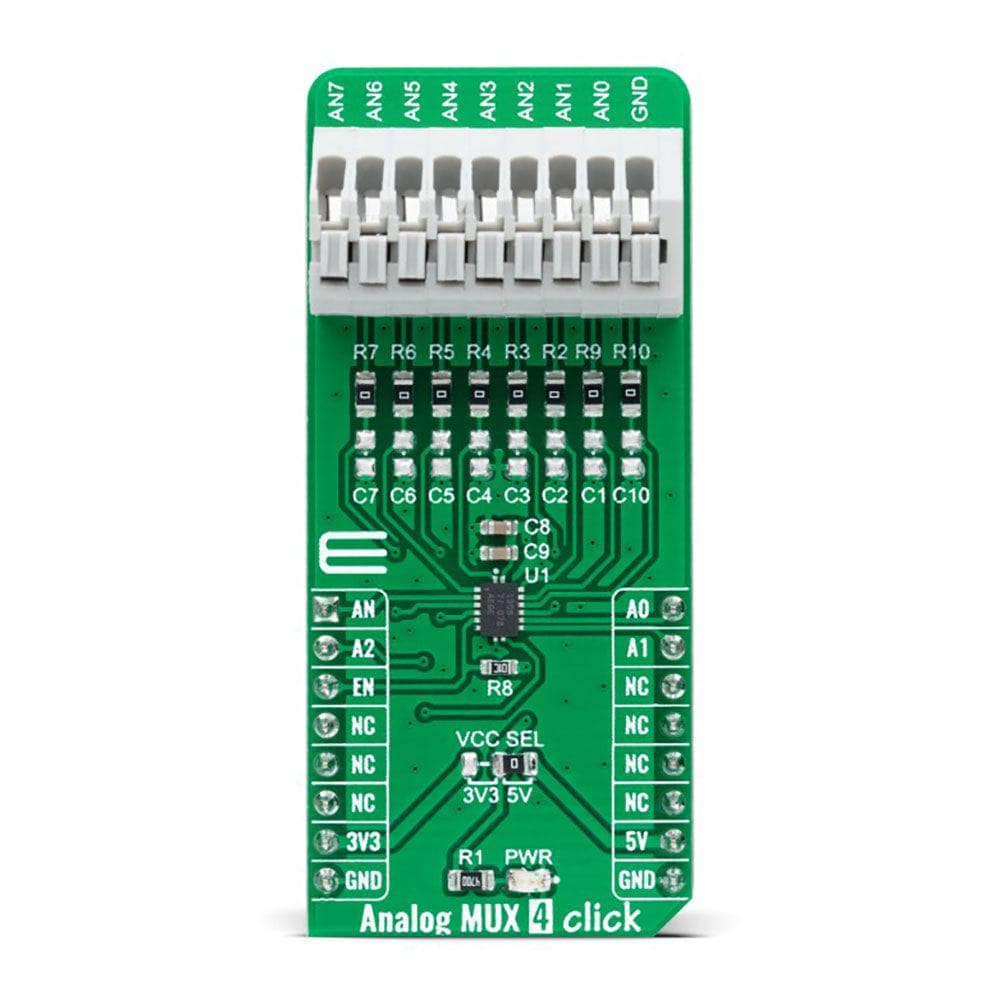
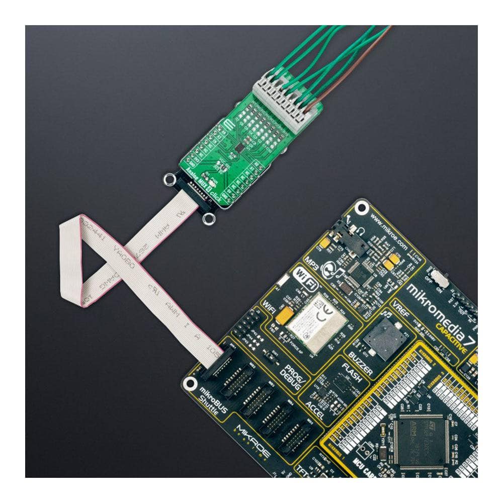
The Analog MUX 4 Click Board™ communicates with MCU using several GPIO pins. It can be enabled or disabled through the EN pin routed to the CS pin of the mikroBUS™ socket; hence, offering a switch operation to turn ON/OFF power delivery to the TMUX1308. It also provides three address signals, labelled from A0 to A2 and routed to the PWM, INT, and RST pins of the mikroBUS™ socket, that control the switch configuration and determine the activation of the desired analog input channel based on their setup. Also, each analog input has a jumper for its hardware activation or deactivation and capacitors for additional filtering of the input channels.
The Analog MUX 4 Click Board™ can operate with both 3.3V and 5V logic voltage levels selected via the VCC SEL jumper. This way, it is allowed for both 3.3V and 5V capable MCUs to use the communication lines properly. However, the Click board™ comes equipped with a library containing easy-to-use functions and an example code that can be used, as a reference, for further development.
SPECIFICATIONS
| Type | Measurements |
| Applications | Can be used for various applications, from industrial to instrumentation, consumer, communications, and more |
| On-board modules | TMUX1308 - general-purpose 8:1 single-ended CMOS analog multiplexer from Texas Instruments |
| Key Features | Injection current control, back-powering protection, bidirectional signal path, Break-Before-Make switching, VCC range signal handling, TTL/CMOS-logic compatible, pin-controllable, and more |
| Interface | Analog,GPIO |
| Compatibility | mikroBUS |
| Click board size | L (57.15 x 25.4 mm) |
| Input Voltage | 3.3V or 5V |
PINOUT DIAGRAM
This table shows how the pinout of the Analog MUX 4 Click Board™ corresponds to the pinout on the mikroBUS™ socket (the latter shown in the two middle columns).
| Notes | Pin | Pin | Notes | ||||
|---|---|---|---|---|---|---|---|
| Analog Signal | AN | 1 | AN | PWM | 16 | A0 | Switch Control 0 |
| Switch Control 2 | A2 | 2 | RST | INT | 15 | A1 | Switch Control 1 |
| Enable | EN | 3 | CS | RX | 14 | NC | |
| NC | 4 | SCK | TX | 13 | NC | ||
| NC | 5 | MISO | SCL | 12 | NC | ||
| NC | 6 | MOSI | SDA | 11 | NC | ||
| Power Supply | 3.3V | 7 | 3.3V | 5V | 10 | 5V | Power Supply |
| Ground | GND | 8 | GND | GND | 9 | GND | Ground |
ONBOARD SETTINGS AND INDICATORS
| Label | Name | Default | Description |
|---|---|---|---|
| LD1 | PWR | - | Power LED Indicator |
| JP1 | VCC SEL | Left | Logic Level Voltage Selection 3V3/5V: Left position 3V3, Right position 5V |
ANALOG MUX 4 CLICK ELECTRICAL SPECIFICATIONS
| Description | Min | Typ | Max | Unit |
|---|---|---|---|---|
| Supply Voltage | 3.3 | - | 5 | V |
| Analog Input Range | 0 | - | 5 | V |
| ON-State Resistance | - | - | 195 | Ω |
| Operating Temperature Range | -40 | 25 | +120 | °C |
| General Information | |
|---|---|
Part Number (SKU) |
MIKROE-4795
|
Manufacturer |
|
| Physical and Mechanical | |
Weight |
0.02 kg
|
| Other | |
EAN |
8606027383687
|
Frequently Asked Questions
Have a Question?
Be the first to ask a question about this.