


Mikroelektronika d.o.o.
SKU: MIKROE-4794RTC 13 Click Board
RTC 13 Click Board
Couldn't load pickup availability
Key Features
- Can be used for various time-keeping applications, including high-duration timers, metering, daily alarms, low standby power applications, and many more
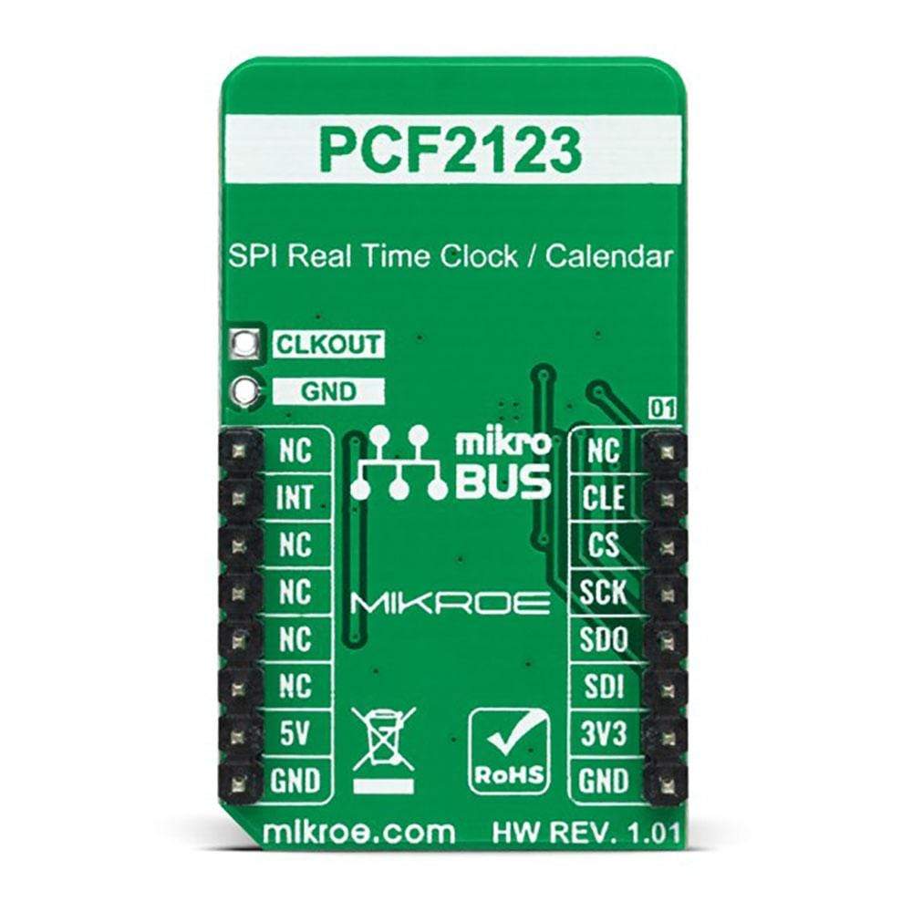
- Based on the PCF2123 - SPI configurable real-time clock/calendar optimized for low power operations from NXP Semiconductors
- Low power consumption, clock/calendar feature, freely programmable timer and alarm with interrupt capability, battery back-up, programmable square wave clock output, and more
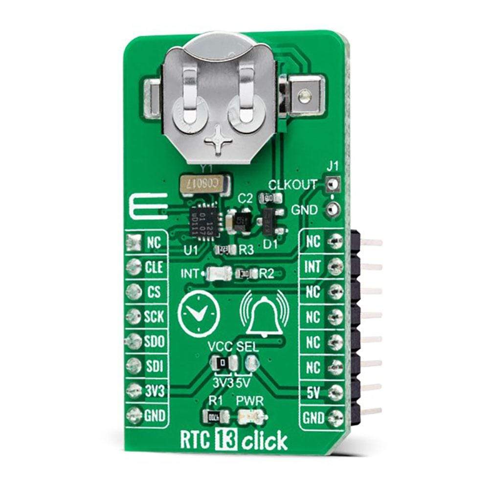
The RTC 13 Click Board™ is a compact add-on board that accurately keeps the time of a day. This board features the PCF2123, an SPI configurable real-time clock/calendar optimized for low power operations from NXP Semiconductors. The PCF2123 provides year, month, day, weekday, hours, minutes, and seconds based on a 32.768kHz quartz crystal. Data is transferred serially via an SPI interface with a maximum data rate of 6.25 Mbit/s. An alarm and timer function is also available, providing the possibility to generate a wake-up signal on an interrupt line, in addition to a programmable square-wave clock output.
The RTC 13 Click Board™ is suitable for various time-keeping applications, including high-duration timers, metering, daily alarms, low standby power applications, and many more.


How Does The RTC 13 Click Board™ Work?
The RTC 13 Click Board™ as its foundation uses the PCF2123, an SPI configurable real-time clock/calendar optimized for low power operations from NXP Semiconductors. It contains sixteen 8-bit registers with an auto-incrementing address counter, an on-chip 32.768kHz oscillator with two integrated load capacitors, a frequency divider that provides the source clock for the RTC, and a programmable clock output. The integrated oscillator ensures year, month, day, weekday, hours, minutes, and seconds, making this Click board™ suitable for various time-keeping applications such as high-duration timers, daily alarms, and many more.
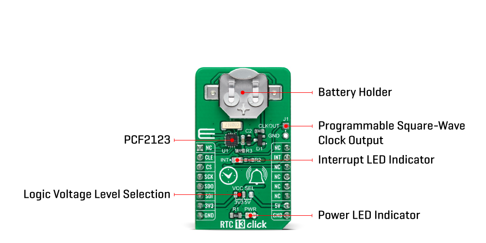
The PCF2123 communicates with MCU using the standard SPI serial interface with a maximum frequency of 8MHz, where data transfers serially with a maximum data rate of 6.25 Mbit/s. An alarm and timer function is also available, providing the possibility to generate a wake-up signal on an interrupt line, available on the INT pin of the mikroBUS™ socket, and indicated by a red LED marked as INT.
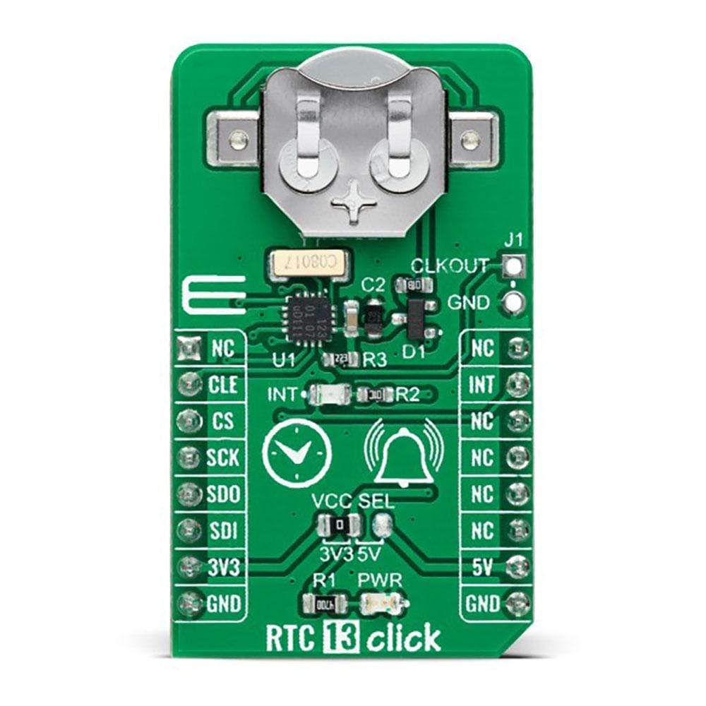
Besides, the RTC 13 Click Board™ also has an onboard header labeled CLKOUT, which provides a programmable square-wave output clock signal controlled by one GPIO pin, a CLE pin routed to the RTS pin the mikroBUS™ socket. Frequencies of 32.768kHz, representing a default value down to 1Hz, can be generated and used as a system and MCU clock, input to a charge pump, or calibration of the oscillator.
The most common RTC configuration, like this one, is a battery-backed up, which maintains time and continues its work without interruption in the event of a power failure. That's why, in addition to the PCF2123, the RTC 13 Click is equipped with a button cell battery holder compatible with the 3000TR battery holder, suitable for 12mm Coin Cell batteries.
The RTC 13 Click Board™ can operate with both 3.3V and 5V logic voltage levels selected via the VCC SEL jumper. This way, it is allowed for both 3.3V and 5V capable MCUs to use the SPI communication lines properly. However, the Click board™ comes equipped with a library containing easy-to-use functions and an example code that can be used, as a reference, for further development.
Specifications
| Type | RTC |
| Applications | Can be used for various time-keeping applications, including high-duration timers, metering, daily alarms, low standby power applications, and many more |
| On-board modules | PCF2123 - SPI configurable real-time clock/calendar optimized for low power operations from NXP Semiconductors |
| Key Features | Low power consumption, clock/calendar feature, freely programmable timer and alarm with interrupt capability, battery back-up, programmable square wave clock output, and more |
| Interface | SPI |
| Compatibility | mikroBUS |
| Click board size | M (42.9 x 25.4 mm) |
| Input Voltage | 3.3V or 5V |
Pinout diagram
This table shows how the pinout on the RTC 13 Click Board™ corresponds to the pinout on the mikroBUS™ socket (the latter shown in the two middle columns).
| Notes | Pin | Pin | Notes | ||||
|---|---|---|---|---|---|---|---|
| NC | 1 | AN | PWM | 16 | NC | ||
| Clock Output Enable | CLE | 2 | RST | INT | 15 | INT | Interrupt |
| SPI Chip Select | CS | 3 | CS | RX | 14 | NC | |
| SPI Clock | SCK | 4 | SCK | TX | 13 | NC | |
| SPI Data OUT | SDO | 5 | MISO | SCL | 12 | NC | |
| SPI Data IN | SDI | 6 | MOSI | SDA | 11 | NC | |
| Power Supply | 3.3V | 7 | 3.3V | 5V | 10 | 5V | Power Supply |
| Ground | GND | 8 | GND | GND | 9 | GND | Ground |
Onboard settings and indicators
| Label | Name | Default | Description |
|---|---|---|---|
| LD1 | PWR | - | Power LED Indicator |
| LD2 | INT | - | Interrupt LED Indicator |
| JP1 | VCC SEL | Left | Logic Level Voltage Selection 3V3/5V: Left position 3V3, Right position 5V |
| J1 | CLKOUT | Unpopulated | Programmable Square Wave Clock Output Header |
RTC 13 Click electrical specifications
| Description | Min | Typ | Max | Unit |
|---|---|---|---|---|
| Supply Voltage | 3.3 | - | 5 | V |
| Operating Temperature Range | - | 32.768 | - | kHz |
| Operating Temperature Range | -40 | +25 | +85 | °C |
Software Support
We provide a library for the RTC 13 Click Board™ as well as a demo application (example), developed using MikroElektronika compilers. The demo can run on all the main MikroElektronika development boards.
The package can be downloaded/installed directly from NECTO Studio Package Manager(recommended way), downloaded from our LibStock™ or found on Mikroe Github account.
Library Description
This library contains API for the RTC 13 Click Board™ driver.
Key Functions
rtc13_get_time- RTC 13 get time function.rtc13_set_time- RTC 13 set time function.rtc13_get_date- RTC 13 get date function.
Example Description
This is an example that demonstrates the use of the RTC 13 Click Board™.
void application_task ( void )
{
    rtc13_get_time( &rtc13, &time );
    Delay_ms( 1 );
    rtc13_get_date( &rtc13, &date );
    Delay_ms( 1 );

    if ( time.sec != new_sec )
	{
        log_printf( &logger, "  Date      : %.2d-%.2d-%.2drn", ( uint16_t ) date.day, ( uint16_t ) date.month, ( uint16_t ) date.year );
        log_printf( &logger, "  Time      : %.2d:%.2d:%.2drn", ( uint16_t ) time.hours, ( uint16_t ) time.min, ( uint16_t ) time.sec );
        log_printf( &logger, "- - - - - - - - - - - -rn" );
        new_sec = time.sec;
        Delay_ms( 1 );
     }
}
The full application code, and ready to use projects can be installed directly from NECTO Studio Package Manager(recommended way), downloaded from our LibStock™ or found on Mikroe Github account.
Other Mikroe Libraries used in the example:
- MikroSDK.Board
- MikroSDK.Log
- Click.RTC13
Additional Notes and Information
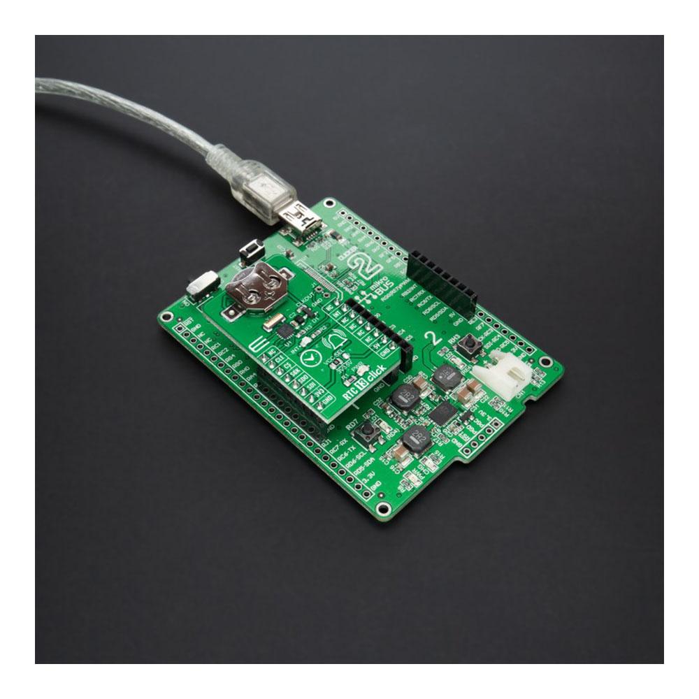
Depending on the development board you are using, you may need a USB UART click, USB UART 2 click or RS232 click to connect to your PC, for development systems with no UART to USB interface available on the board. The terminal available in all MikroElektronika compilers, or any other terminal application of your choice, can be used to read the message.
mikroSDK
The RTC 13 Click Board™ is supported with mikroSDK - MikroElektronika Software Development Kit. To ensure proper operation of mikroSDK compliant Click board™ demo applications, mikroSDK should be downloaded from the LibStock and installed for the compiler you are using.
RTC 13 Click Board
Frequently Asked Questions
Have a Question?
Be the first to ask a question about this.