


Mikroelektronika d.o.o.
SKU: MIKROE-4780Accel 4 Click Board
Accel 4 Click Board
Couldn't load pickup availability
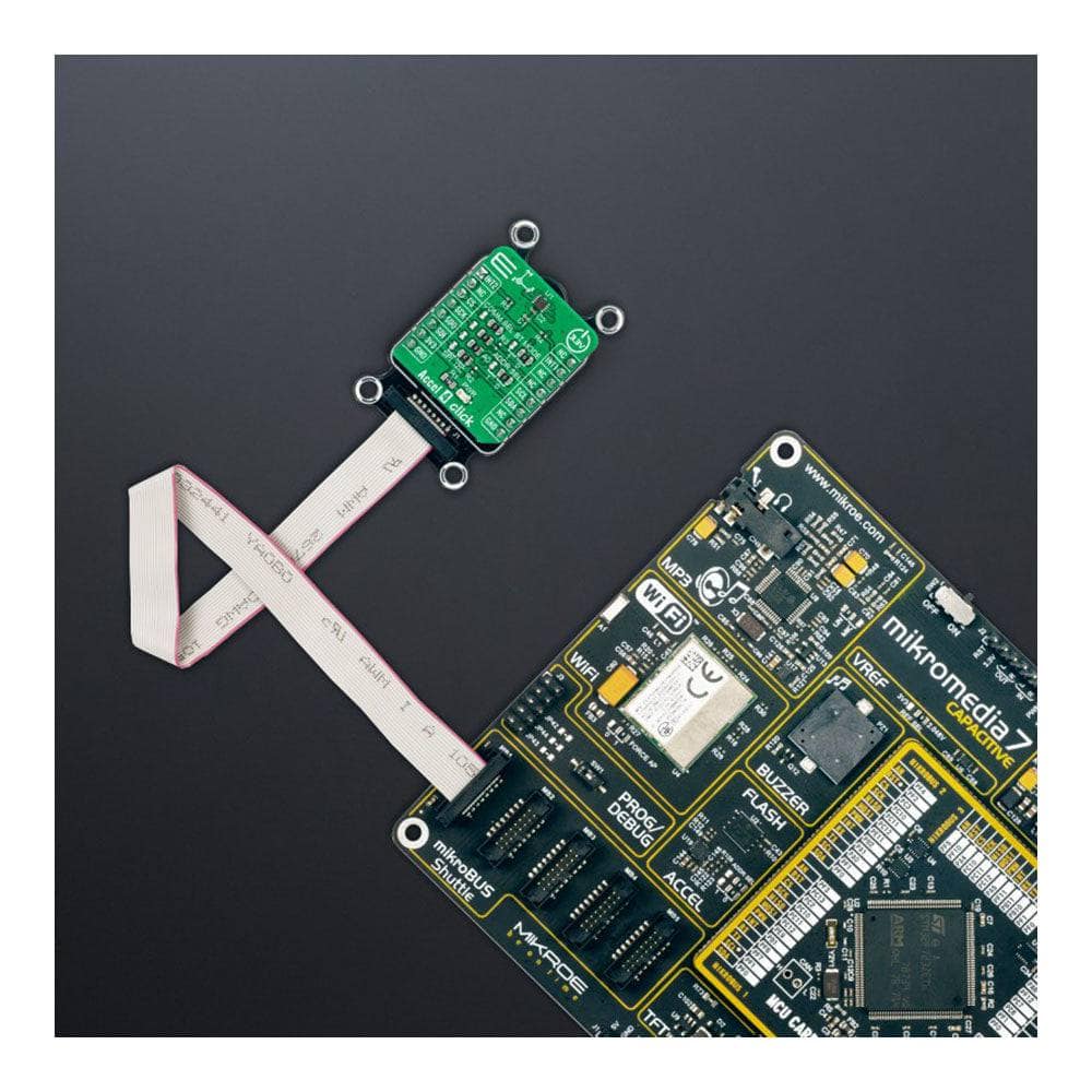
The Accel 4 Click Board™ is a compact add-on board with an acceleration sensor. This board features the FXLS8974CF, a 12-bit three-axis accelerometer from NXP Semiconductors. It allows selectable full-scale acceleration measurements in ranges of ±2g, ±4g, ±8g, or ±16g in three axes with a configurable host interface that supports both SPI and I2C serial communication. The FXLS8974CF supports both high-performance and low-power operating modes, allowing maximum flexibility to meet the resolution and power needs for various unique use cases. This Click board™ is suitable for a wide range of automotive (convenience and security), industrial, and medical IoT applications that require ultra-low-power Wake-Up on the motion.
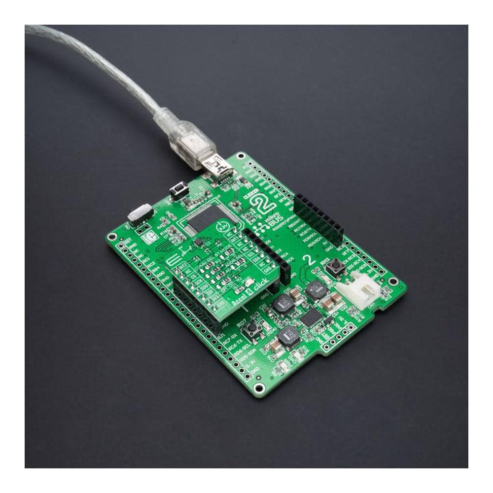
The Accel 4 Click Board™ is supported by a mikroSDK compliant library, which includes functions that simplify software development. This Click board™ comes as a fully tested product, ready to be used on a system equipped with the mikroBUS™ socket.
Note: This Click board™, alongside FXLS8974CF, also represents a reference design for the FXLS8964AF and FXLS8967AF.
How Does The Accel 4 Click Board™ Work?
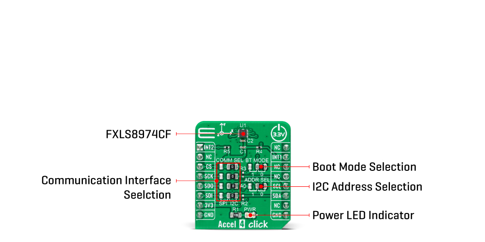
The Accel 4 Click Board™ as its foundation uses the FXLS8974CF, a highly reliable digital triaxial acceleration from NXP Semiconductors. The FXLS8974CF is highly configurable with a programmable acceleration range of ±2g, ±4g, ±8g, or ±16g, capable of measuring accelerations with selectable output data rates. It supports high-performance and low-power operating modes, allowing maximum flexibility to meet the resolution and power needs for various use cases from automotive (convenience and security) through industrial IoT to some consumer devices.
This sensor includes advanced digital features such as the SDCD block for inertial event detection, auto wake-sleep, and a 32 sample FIFO/LIFO buffer. Besides, it has an embedded temperature sensor with an 8 bits resolution, sensitivity of 1°C/LSB, and measurement range from -40°C up to +105°C. Selectable ODRs (Output Data Rate) of the FXLS8974CF go up to 3200Hz, alongside Flexible Performance mode, allowing custom ODRs with a programmable decimation (resolution) and idle-time settings.
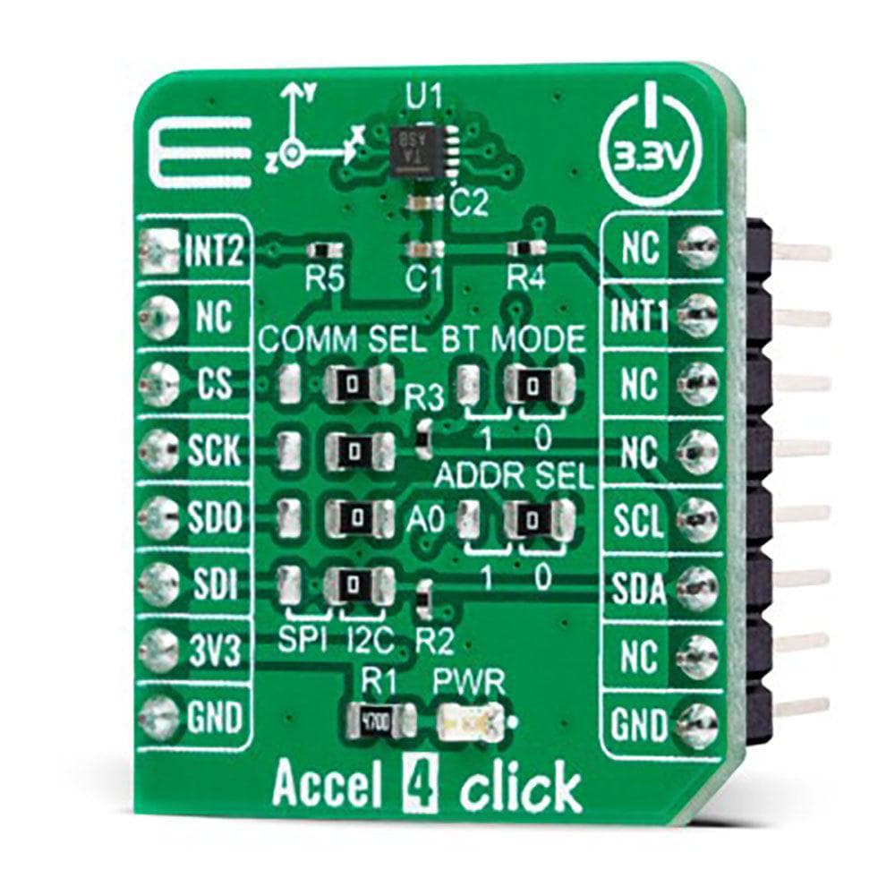
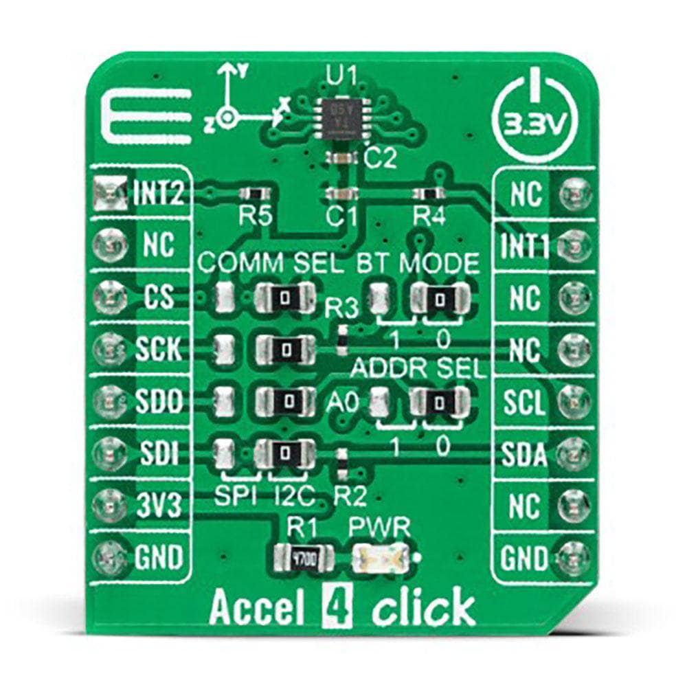
The Accel 4 Click Board™ allows using both I2C and SPI interfaces with a maximum frequency of 1MHz for I2C and 4MHz for SPI communication. The selection can be made by positioning SMD jumpers labelled as COMM SEL in an appropriate position. Note that all the jumpers' positions must be on the same side, or the Click board™ may become unresponsive. While the I2C interface is selected, the FXLS8974CF allows choosing the least significant bit (LSB) of its I2C slave address using the SMD jumper labelled ADDR SEL.
The FXLS8974CF also possesses two interrupts, INT1 and INT2, routed to the INT and AN pins on the mikroBUS™ socket used to signal MCU that an event has been sensed, entirely programmed by the user through the I2C/SPI interface. Also, this Click board™ provides the ability to use the boot mode of the FXLS8974CF by positioning SMD jumpers labelled as BT MODE to an appropriate position. Depending on the selected position, the device can be set in the default operating mode by setting the jumper to position 0 or in Motion Detection Mode to position 1.
The Accel 4 Click Board™ can be operated only with a 3.3V logic voltage level. The board must perform appropriate logic voltage level conversion before using MCUs with different logic levels. However, the Click board™ comes equipped with a library containing functions and an example code that can be used, as a reference, for further development.
SPECIFICATIONS
| Type | Motion |
| Applications | Can be used for a wide range of automotive (convenience and security), industrial, and medical IoT applications |
| On-board modules | FXLS8974CF - highly reliable digital triaxial acceleration from NXP Semiconductors |
| Key Features | Low power consumption, high performance and resolution, selectable ODRs, flexible sensor data change detection function, integrated interrupt features, selectable serial interface, and more |
| Interface | I2C,SPI |
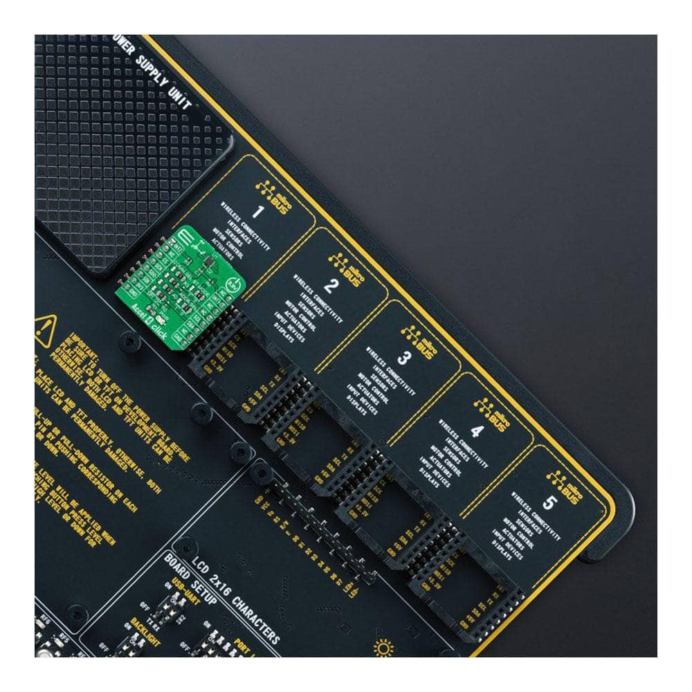
| Compatibility | mikroBUS |
| Click board size | S (28.6 x 25.4 mm) |
| Input Voltage | 3.3V |
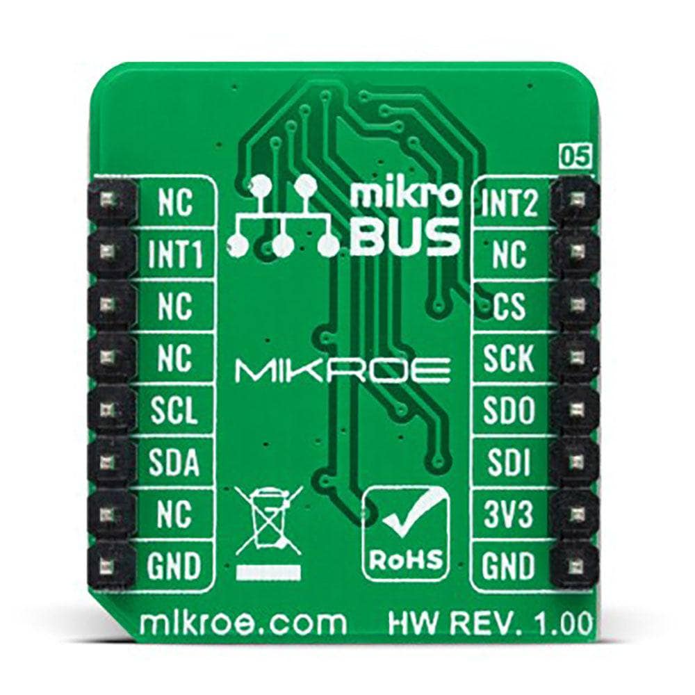
PINOUT DIAGRAM
This table shows how the pinout of the Accel 4 Click Board™ corresponds to the pinout on the mikroBUS™ socket (the latter shown in the two middle columns).
| Notes | Pin | Pin | Notes | ||||
|---|---|---|---|---|---|---|---|
| Interrupt 2 | INT2 | 1 | AN | PWM | 16 | NC | |
| NC | 2 | RST | INT | 15 | INT1 | Interrupt | |
| SPI Chip Select | CS | 3 | CS | RX | 14 | NC | |
| SPI Clock | SCK | 4 | SCK | TX | 13 | NC | |
| SPI Data OUT | SDO | 5 | MISO | SCL | 12 | SCL | I2C Clock |
| SPI Data IN | SDI | 6 | MOSI | SDA | 11 | SDA | I2C Data |
| Power Supply | 3.3V | 7 | 3.3V | 5V | 10 | NC | |
| Ground | GND | 8 | GND | GND | 9 | GND | Ground |
ONBOARD SETTINGS AND INDICATORS
| Label | Name | Default | Description |
|---|---|---|---|
| LD1 | PWR | - | Power LED Indicator |
| JP1-JP4 | COMM SEL | Right | Communication Interface Selection SPI/I2C: Left position SPI, Right position I2C |
| JP5 | ADDR SEL | Right | I2C Address Selection 1/0: Left position 1, Right position 0 |
| JP6 | BT MODE | Right | Boot Mode Selection 1/0: Left position 1, Right position 0 |
ACCEL 4 CLICK ELECTRICAL SPECIFICATIONS
| Description | Min | Typ | Max | Unit |
|---|---|---|---|---|
| Supply Voltage | - | 3.3 | - | V |
| Acceleration Range | ±2 | - | ±16 | g |
| Acceleration Resolution | - | 12 | - | bits |
| Sensitivity (±2 ~ ±16) | 128 | - | 1024 | LSB/g |
| Operating Temperature Range | -40 | +25 | +105 | °C |
Software Support
We provide a library for the Accel 4 Click Board™ as well as a demo application (example), developed using MikroElektronika compilers. The demo can run on all the main MikroElektronika development boards.
The package can be downloaded/installed directly from NECTO Studio The package Manager (recommended), downloaded from our LibStock™ or found on the MikroE Github account.
Library Description
This library contains API for the Accel 4 Click Board™ driver.
Key Functions
accel4_get_int1- Get interrupt 1 pin state.accel4_axes_get_resolution- Reads current resolution of output data.accel4_get_axes_data- Accel data reading.
Example Description
This example is a showcase of the ability of the device to read 3-axis data in a variety of 3 resolutions, the ability to configure two interrupt pins for user needs etc.
void application_task ( void )
{
    if ( accel4_get_int1( &accel4 ) )
    {
        accel4_axes_t axes;
        accel4_get_axes_data( &accel4, &axes );

        log_printf( &logger, " > X: %.2frn", axes.x );
        log_printf( &logger, " > Y: %.2frn", axes.y );
        log_printf( &logger, " > Z: %.2frn", axes.z );
        log_printf( &logger, "*****************************************rn" );
        Delay_ms( 300 );
    }
}
The complete application code and ready-to-use projects can be installed directly from NECTO Studio Package Manager(recommended way), downloaded from our LibStock™ or found on the Mikroe GitHub account.
Other mikroE Libraries used in the example:
- MikroSDK.Board
- MikroSDK.Log
- Click.Accel4
Additional Notes and Information
Depending on the development board you are using, you may need USB UART Click Board™, USB UART 2 Click Board™ or RS232 Click Board™ to connect to your PC for development systems with no UART to USB interface available on the board. The terminal available in all MikroElektronika compilers, or any other terminal application of your choice, can be used to read the message.
MIKROSDK
The Accel 4 Click Board™ is supported with mikroSDK - MikroElektronika Software Development Kit. To ensure proper operation of mikroSDK compliant Click board™ demo applications, mikroSDK should be downloaded from the LibStock and installed for the compiler you are using.
Accel 4 Click Board
Frequently Asked Questions
Have a Question?
Be the first to ask a question about this.