


Mikroelektronika d.o.o.
SKU: MIKROE-4778Magneto 9 Click Board
Magneto 9 Click Board
Couldn't load pickup availability
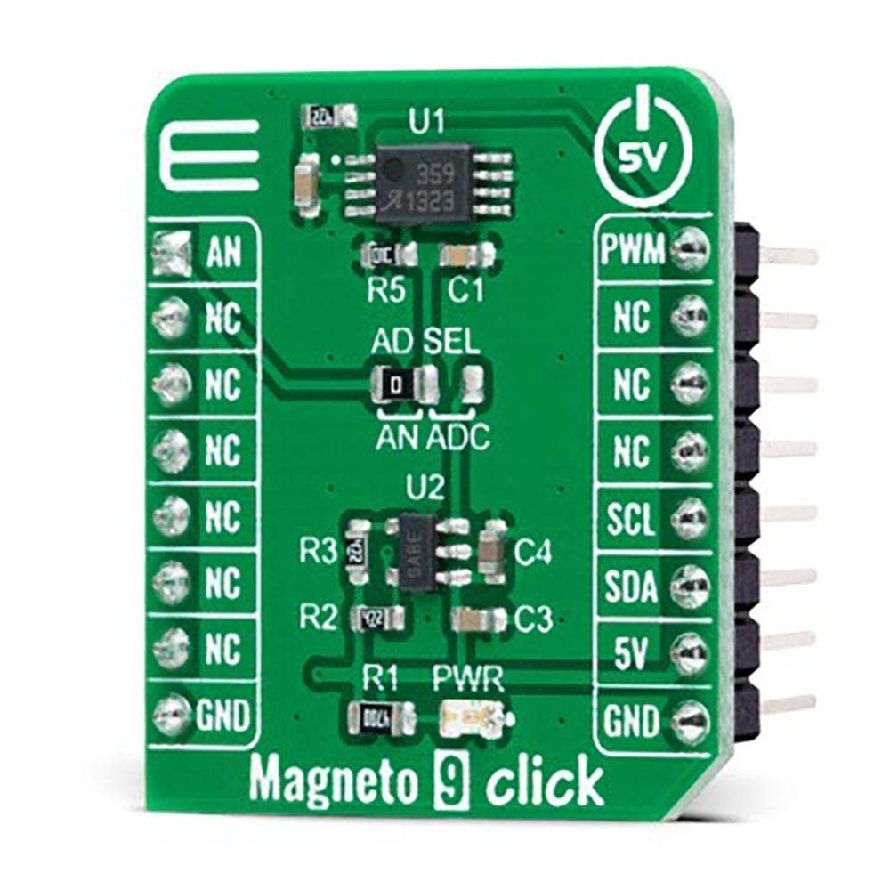
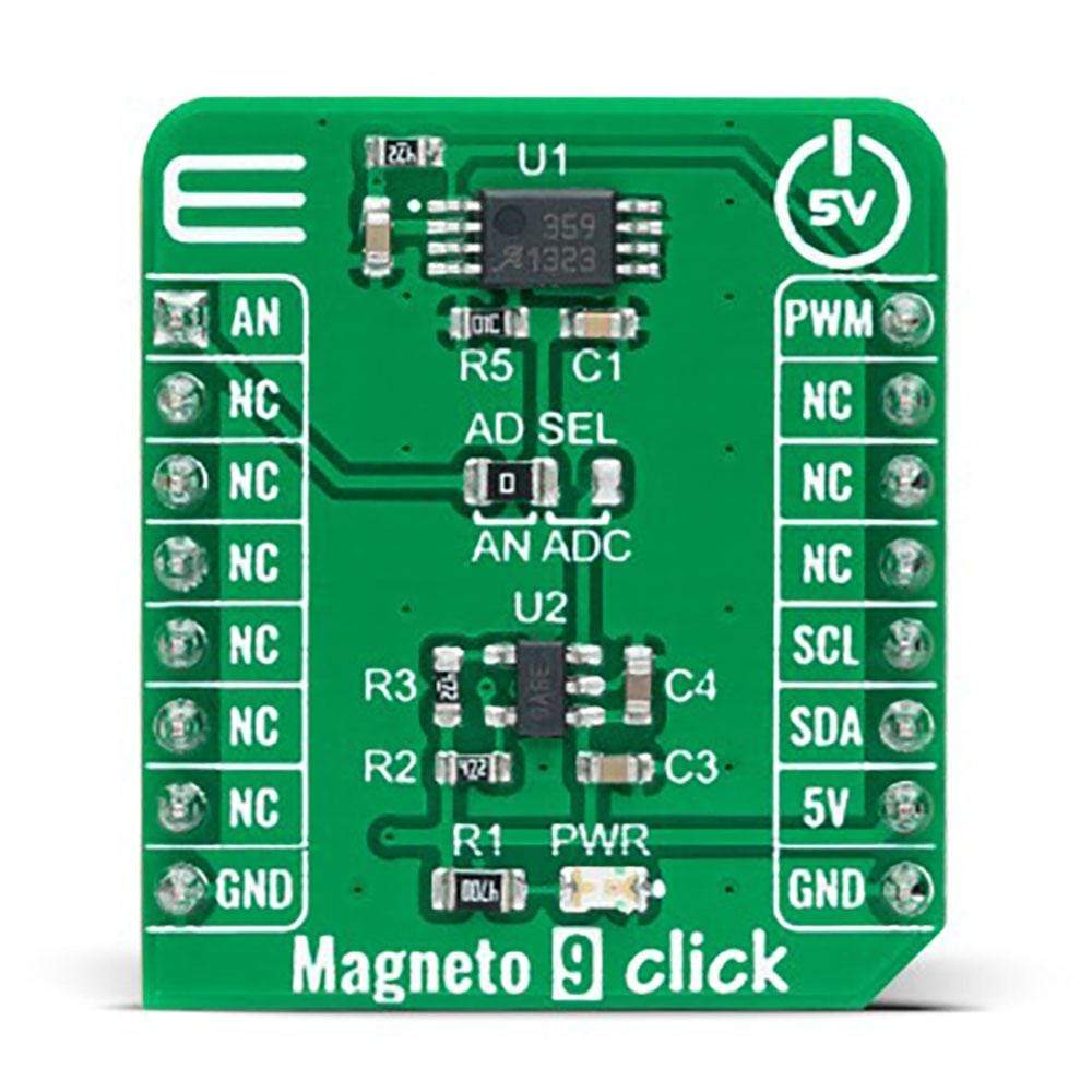
The Magneto 9 Click Board™ is a compact add-on board that contains a low-power, accurate, and reliable magnetic sensing device. This board features the A1359, dual tracking output linear hall-effect sensor from Allegro MicroSystems. This ratiometric Hall-effect sensor provides an analogue voltage and a PWM signal with a duty cycle proportional to the applied magnetic field. It comes with factory-programmed offset, sensitivity, and polarity, where the PWM output tracks the analogue output to within a +/-3% mismatch. This Click Board™ is the most suitable for use in automotive and industrial applications such as displacement and angular position, which requires high accuracy in conjunction with redundant outputs.
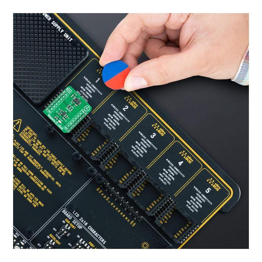
The Magneto 9 Click Board™ is supported by a mikroSDK compliant library, which includes functions that simplify software development. This Click Board™ comes as a fully tested product, ready to be used on a system equipped with the mikroBUS™ socket.
How Does The Magneto 9 Click Board™ Work?
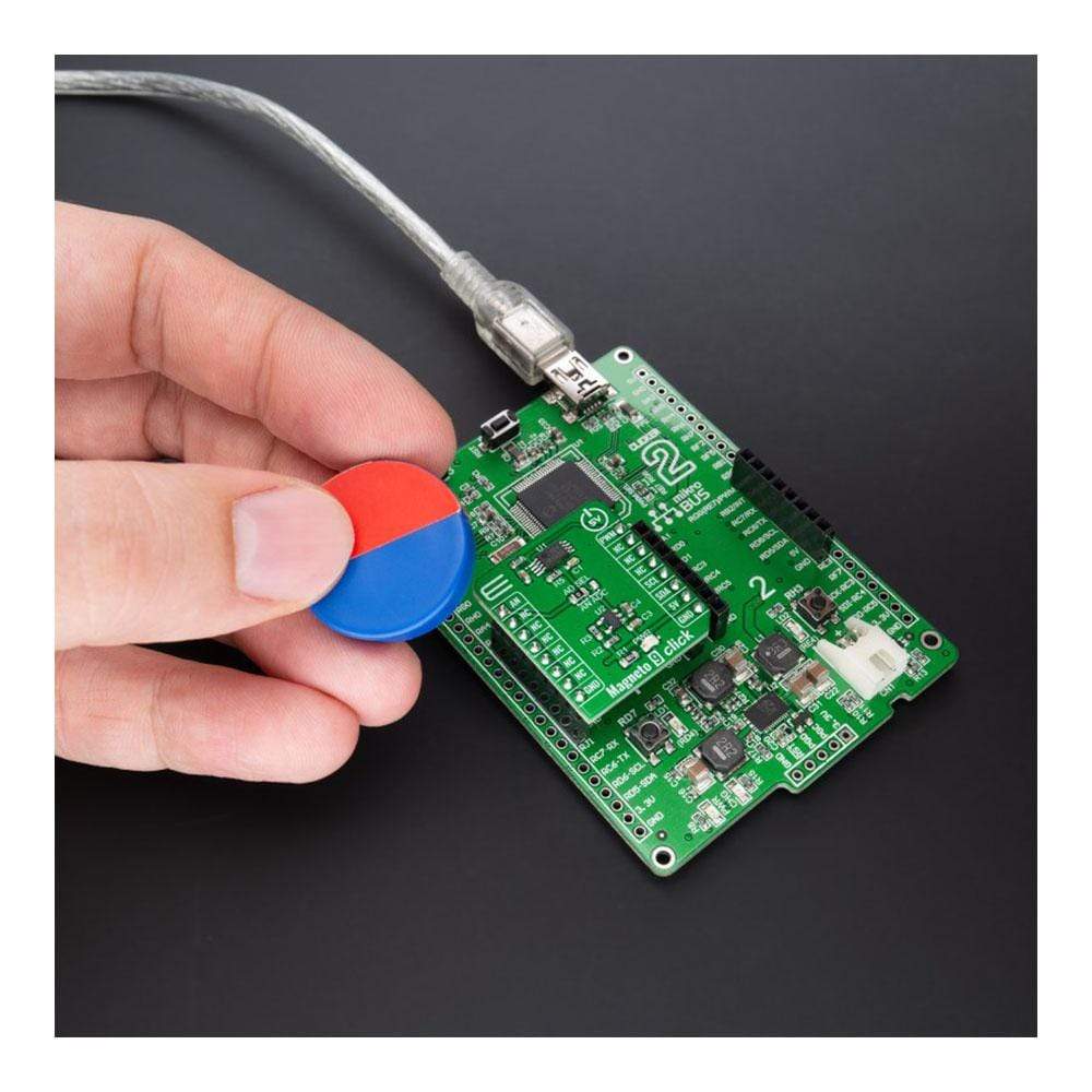
The Magneto 9 Click Board™ as its foundation uses the A1359, a one-time programmable, dual tracking output, linear Hall-effect sensor from Allegro MicroSystems. It provides a dual analogue/PWM output, where the PWM output tracks the analogue output to within a +/-3% mismatch. It comes with factory-programmed output polarity; in this case, a forward polarity meaning that output voltage increases with increasing positive (south) applied magnetic field. The A1359 is targeted at the automotive market with end applications to include electronic power steering (torque sensing), transmission component position, brake and clutch cylinder position, and various other industrial applications.
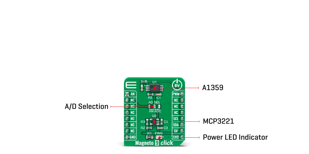
The analogue output signal of the A1359 can be converted to a digital value using MCP3221, a successive approximation A/D converter with a 12-bit resolution from Microchip, using a 2-wire I2C compatible interface, or can be sent directly to an analogue pin of the mikroBUS™ socket labelled as AN. Selection can be performed by onboard SMD jumper labelled as AD SEL to an appropriate position marked as AN and ADC.
The MCP3221 provides one single-ended input with low power consumption, a low maximum conversion current, and a Standby current of 250μA and 1μA, respectively. Data can be transferred at rates of up to 100kbit/s in the Standard and 400kbit/s in the Fast Mode. Also, maximum sample rates of 22.3kSPS with the MCP3221 are possible in a Continuous-Conversion Mode with a clock rate of 400kHz.
This Click board™ operates only with a 5V logic voltage level. The board must perform appropriate logic voltage level conversion before use with MCUs with different logic levels. However, the Click board™ comes equipped with a library containing functions and an example code that can be used, as a reference, for further development.
Specifications
| Type | Magnetic |
| Applications | Can be used in automotive and industrial applications such as displacement and angular position, which requires high accuracy in conjunction with redundant outputs |
| On-board modules | A1359 - dual tracking output linear hall-effect sensor from Allegro MicroSystems |
| Key Features | Low power consumption, factory-programmed offset, sensitivity, and polarity, dual-output (analog and PWM), accuracy, forward polarity, possibility of signal processing in analog and digital form, and more |
| Interface | Analog,I2C,PWM |
| Compatibility | mikroBUS |
| Input Voltage | 5V |
Pinout diagram
This table shows how the pinout on Magneto 9 Click corresponds to the pinout on the mikroBUS™ socket (the latter shown in the two middle columns).
| Notes | Pin | Pin | Notes | ||||
|---|---|---|---|---|---|---|---|
| Analog Signal | AN | 1 | AN | PWM | 16 | PWM | PWM Signal |
| NC | 2 | RST | INT | 15 | NC | ||
| NC | 3 | CS | RX | 14 | NC | ||
| NC | 4 | SCK | TX | 13 | NC | ||
| NC | 5 | MISO | SCL | 12 | SCL | I2C Clock | |
| NC | 6 | MOSI | SDA | 11 | SDA | I2C Data | |
| NC | 7 | 3.3V | 5V | 10 | 5V | Power Supply | |
| Ground | GND | 8 | GND | GND | 9 | GND | Ground |
Onboard settings and indicators
| Label | Name | Default | Description |
|---|---|---|---|
| LD1 | PWR | - | Power LED Indicator |
| JP1 | AD SEL | Left | Output Voltage AD Selection AN/ADC: Left position AN, Right position ADC |
Magneto 9 Click electrical specifications
| Description | Min | Typ | Max | Unit |
|---|---|---|---|---|
| Supply Voltage | - | 5 | - | V |
| Maximum Output Current | - | - | 10 | mA |
| Operating Temperature Range | -40 | +25 | +150 | °C |
Software Support
We provide a library for the Magneto 9 Click as well as a demo application (example), developed using MikroElektronika compilers. The demo can run on all the main MikroElektronika development boards.
The package can be downloaded/installed directly from NECTO Studio Package Manager(recommended way), downloaded from our LibStock™ or found on Mikroe GitHub account.
Library Description
This library contains API for Magneto 9 Click driver.
Key Functions
magneto9_cfg_setup- Config Object Initialization function.magneto9_init- Initialization function.
Example Description
This example demonstrates the use of the Magneto 9 Click board™.
void application_task ( void )
{
    float voltage = 0;

    if ( MAGNETO9_OK == magneto9_read_adc_voltage ( &magneto9, &voltage ) )
    {
        float field_strength = MAGNETO9_VOLTAGE_TO_FIELD_STRENGTH ( voltage );
        log_printf( &logger, " ADC Voltage : %.3f Vrn", voltage );
        log_printf( &logger, " Magnetic field strength : %.3f mTrn", field_strength );
        if ( field_strength < 0 )
        {
            log_printf( &logger, " The North Pole magnetic field prevails.rnn" );
        }
        else
        {
            log_printf( &logger, " The South Pole magnetic field prevails.rnn" );
        }
    }
    Delay_ms( 1000 );
}
The full application code, and ready to use projects can be installed directly from NECTO Studio Package Manager(recommended way), downloaded from our LibStock™ or found on Mikroe GitHub account.
Other mikroE Libraries used in the example:
- MikroSDK.Board
- MikroSDK.Log
- Click.Magneto9
Additional Notes and Information
Depending on the development board you are using, you may need a USB UART click, USB UART 2 click or RS232 click to connect to your PC, for development systems with no UART to USB interface available on the board. The terminal available in all MikroElektronika compilers, or any other terminal application of your choice, can be used to read the message.
mikroSDK
This Click board™ is supported with mikroSDK - MikroElektronika Software Development Kit. To ensure proper operation of mikroSDK compliant Click board™ demo applications, mikroSDK should be downloaded from the LibStock and installed for the compiler you are using.
Magneto 9 Click Board
Frequently Asked Questions
Have a Question?
Be the first to ask a question about this.