


Mikroelektronika d.o.o.
Stepper 18 Click Board™
Stepper 18 Click Board™
SKU: MIKROE-4689
Couldn't load pickup availability
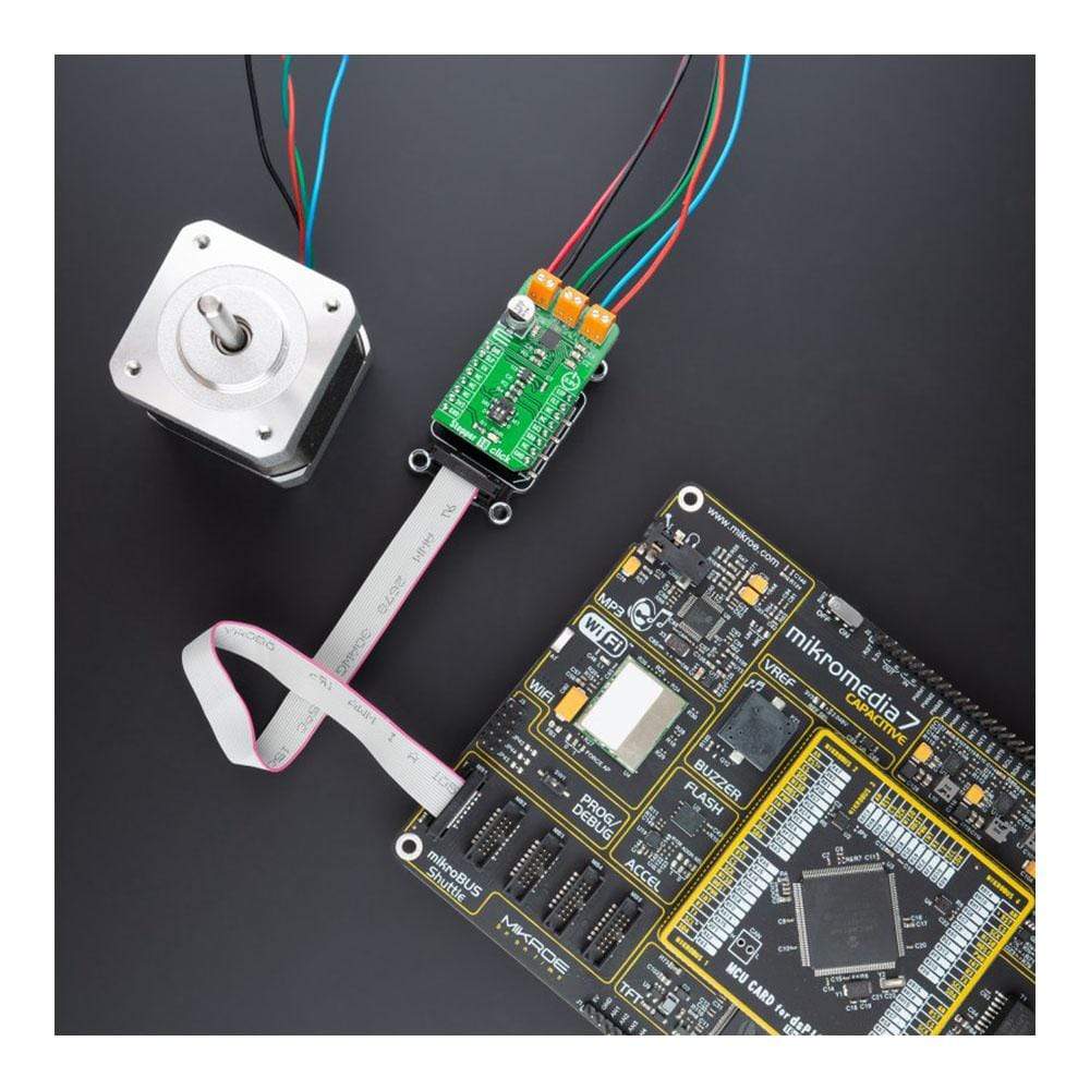
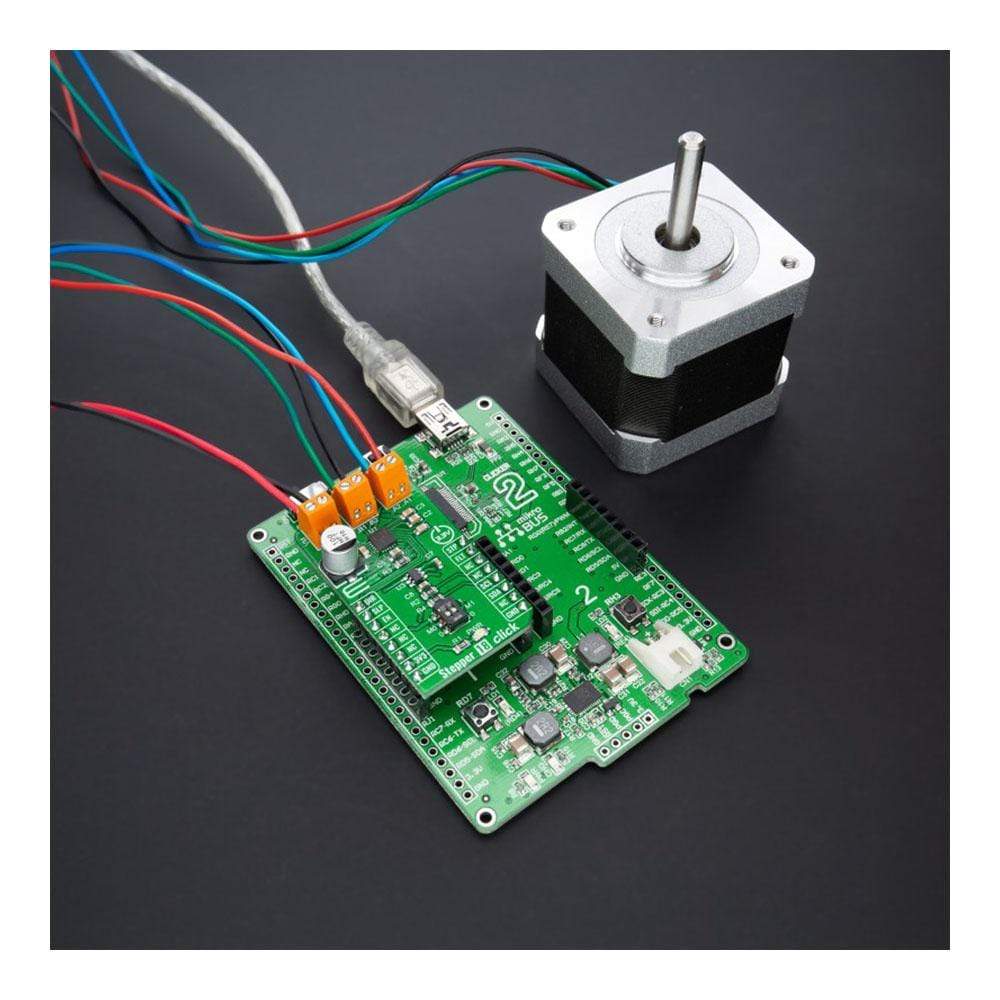
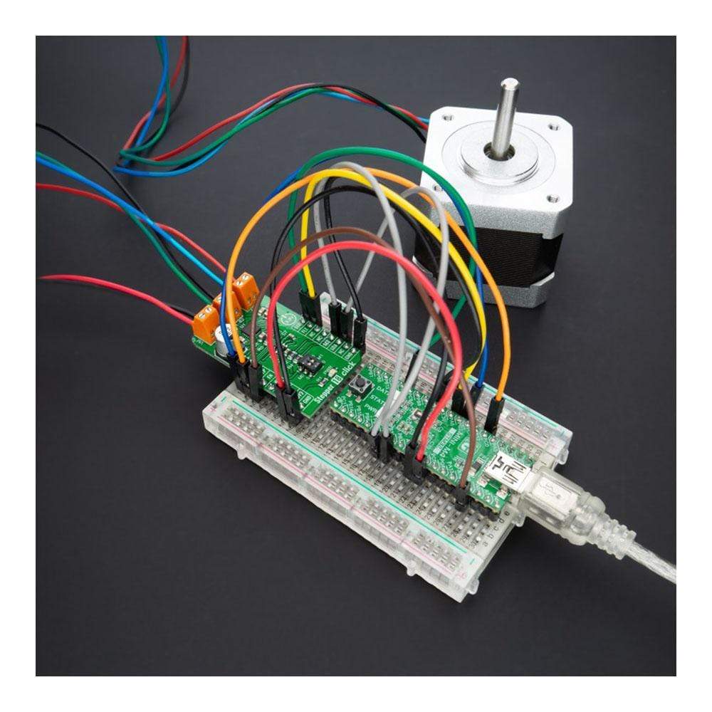
Overview
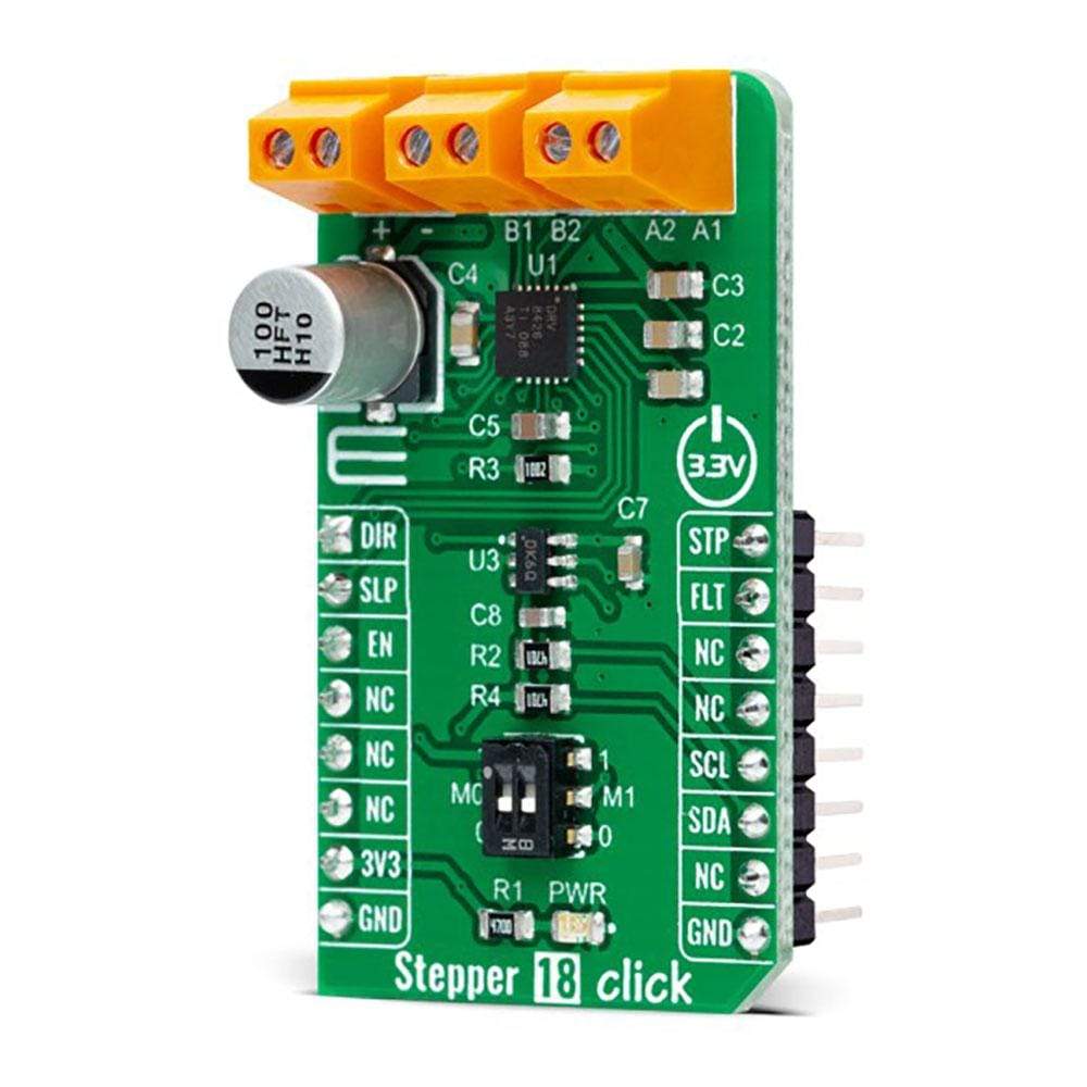
The Stepper 18 Click Board™ is a compact add-on board with a microstepping stepper motor driver. This board features the DRV8426, a stepper motor driver for industrial and consumer applications from Texas Instruments. It is fully integrated with two N-channel power MOSFET H-bridge drivers, a microstepping indexer, and integrated current sensing capable of driving up to 1.5A full-scale output current. A simple STEP/DIR interface allows managing the direction and step rate of the stepper motor up to 1/256 microstepping. This Click Board™ is suitable for driving motors in any application that demands a precise and safe step motor driver.Downloads
How Does The Stepper 18 Click Board™ Work?
The Stepper 18 Click Board™ as its foundation uses the DRV8426, an integrated motor-driver solution for bipolar stepper motors with integrated current sense, 1/256 microstepping, STEP/DIR interface, and smart-tune technology Texas Instruments. It provides the maximum integration by integrating two N-channel power MOSFET H-bridges, current sense resistors and regulation circuitry, and a microstepping indexer capable of driving up to 1.5A full-scale output current.

Stepper motor drivers need to re-circulate the winding current by implementing several decay modes, like slow decay, mixed decay, and fast decay. The DRV8426 comes with smart-tune decay modes, representing a decay mechanism that automatically adjusts for optimal current regulation performance agnostic of voltage, motor speed, variation, and ageing effects. Along with this automatic smart-tune, DRV8426 also provides the traditional decay modes like slow-mixed and mixed decay.
The voltage at the VREF pin adjusts the current regulation set-point obtained by the MCP4726, a 12-bit digital-to-analogue converter from Microchip. Thus, the digital value is converted to the appropriate voltage level (VCC) proportional to the received 12-bit number. The MCP4726 also integrates EEPROM for storing DAC register and configuration bit values and communicates with the MCU through the I2C 2-Wire interface supporting Standard (100 kHz), Fast (400 kHz), and High-Speed (3.4 MHz) I2C modes.
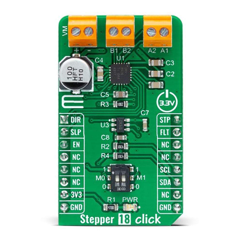
In addition to I2C communication, the Stepper 18 Click also communicates with MCU using several GPIO pins. A simple STEP/DIR interface, labelled as STP and DIR routed to the PWM and AN pins on the mikroBUS™ socket, allows MCU to manage the direction and step rate of the stepper motor. The internal microstepping indexer can execute high-accuracy microstepping without requiring the MCU to handle the winding current level. The indexer can achieve full step, half step, 1/4, 1/8, 1/16, 1/32, 1/64, 1/128, and 1/256 microstepping through the M0 and M1 pins routed to the onboard SMD switch. Also, high microstepping contributes to significant audible noise reduction and smooth motion.
The Enable pin, labelled as EN and routed to the CS pin of the mikroBUS™ socket, optimizes power consumption and is used for power ON/OFF purposes. All circuits, including the interface pins, are inactive in this state, and the DRV8426 is in the form of minimum power consumption. Also, a low-power Sleep feature is included, routed to the RST pin of the mikroBUS™ socket alongside fault-interrupt feature routed to the INT pin of the mikroBUS™ socket. The Sleep Mode allows the system to save power when not actively driving the motor.
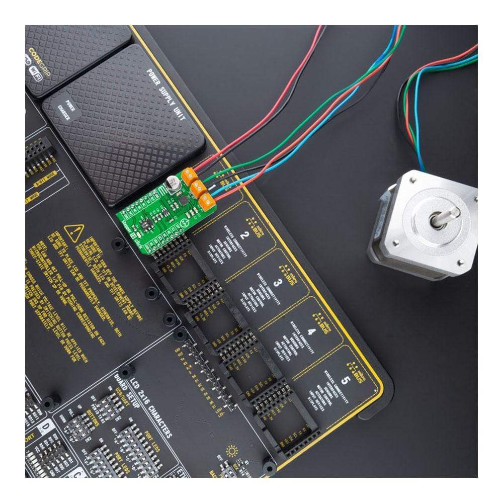
The Stepper 18 Click Board™ supports an external power supply for the motor, which can be connected to the input terminal labelled as VM and should be within the range of 4.5V to 33V, while the stepper motor coils can be connected to the terminals labelled as A1, B2, B1, and A2.
The Stepper 18 Click Board™ can be operated only with a 3.3V logic voltage level. Therefore, the board must perform appropriate logic voltage level conversion before using MCUs with different logic levels. However, the Click board™ comes equipped with a library containing functions and an example code that can be used, as a reference, for further development.
SPECIFICATIONS
| Type | Stepper |
| Applications | Can be used for driving motors in any application that demands a precise and safe step motor driver |
| On-board modules | DRV8426 - an integrated motor-driver solution for bipolar stepper motors with integrated current sense, 1/256 microstepping, STEP/DIR interface, and smart-tune technology Texas Instruments |
| Key Features | Microstepping stepper motor driver (STEP/DIR interface), integrated current sense functionality, smart-tune decay technology, protection features, and more. |
| Interface | I2C,GPIO |
| Compatibility | mikroBUS |
| Click board size | M (42.9 x 25.4 mm) |
| Input Voltage | 3.3V, External |
PINOUT DIAGRAM
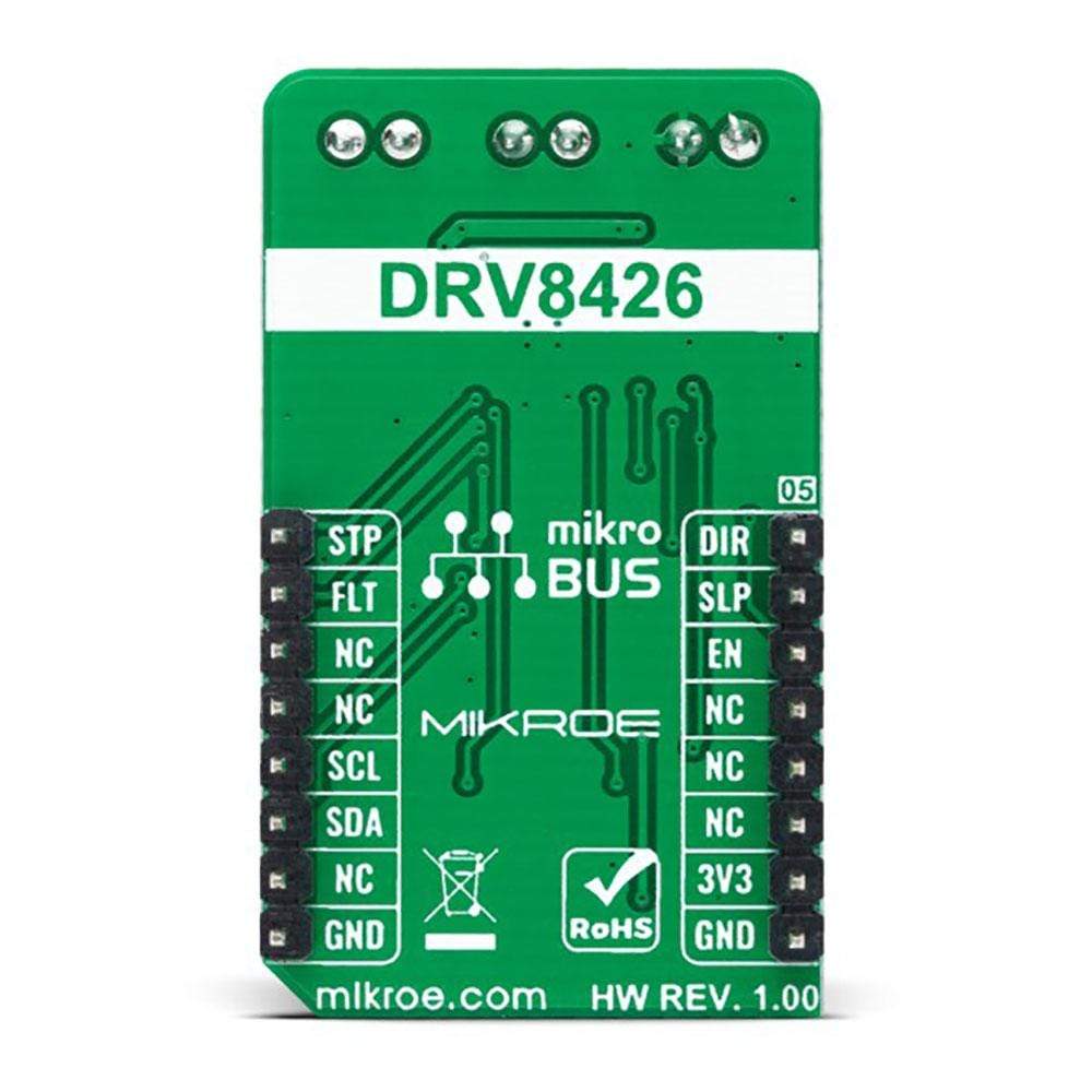
This table shows how the pinout of the Stepper 18 Click Board™ corresponds to the pinout on the mikroBUS™ socket (the latter shown in the two middle columns).
| Notes | Pin |  |
Pin | Notes | |||
|---|---|---|---|---|---|---|---|
| Stepping Direction | DIR | 1 | AN | PWM | 16 | STP | Step-Rate |
| Sleep Mode | SLP | 2 | RST | INT | 15 | FLT | Fault Indicator |
| Enable | EN | 3 | CS | RX | 14 | NC | |
| NC | 4 | SCK | TX | 13 | NC | ||
| NC | 5 | MISO | SCL | 12 | SCL | I2C Clock | |
| NC | 6 | MOSI | SDA | 11 | SDA | I2C Data | |
| Power Supply | 3.3V | 7 | 3.3V | 5V | 10 | NC | |
| Ground | GND | 8 | GND | GND | 9 | GND | Ground |
ONBOARD SETTINGS AND INDICATORS
| Label | Name | Default | Description |
|---|---|---|---|
| LD1 | PWR | - | Power LED Indicator |
| SW1 | - | Down | Step Mode Selection |
STEPPER 18 CLICK ELECTRICAL SPECIFICATIONS
| Description | Min | Typ | Max | Unit |
|---|---|---|---|---|
| Supply Voltage VCC | - | 3.3 | - | V |
| External Supply Voltage VM | 4.5 | - | 33 | V |
| Motor Full-Scale Current | - | - | 1.5 | A |
| Operating Temperature Range | -40 | +25 | +125 | °C |
| General Information | |
|---|---|
Part Number (SKU) |
MIKROE-4689
|
Manufacturer |
|
| Physical and Mechanical | |
Weight |
0.02 kg
|
| Other | |
EAN |
8606027383151
|
Frequently Asked Questions
Have a Question?
Be the first to ask a question about this.