


Mikroelektronika d.o.o.
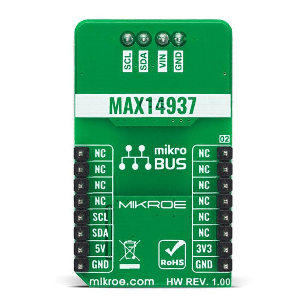
I2C Isolator 4 Click Board™
I2C Isolator 4 Click Board™
SKU: MIKROE-4675
Couldn't load pickup availability
Key Features
Overview
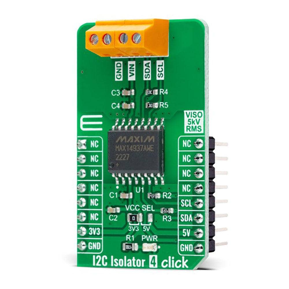
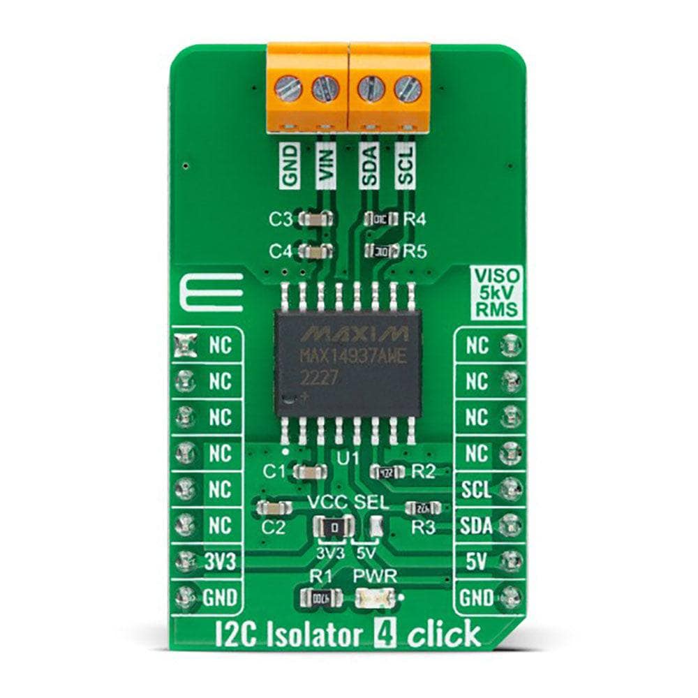
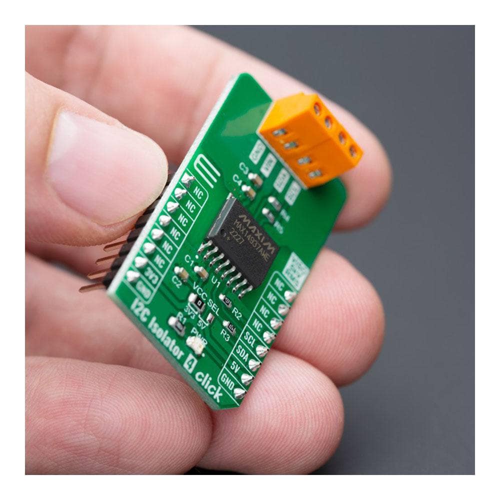
The I2C Isolator 4 Click Board™ is a compact add-on board that offers completely isolated bidirectional communication. This board features the MAX14937, a two-channel, 5kVRMS I2C digital isolator from Analog Devices. The MAX14937 provides two bidirectional, open-drain channels for applications that require data to be transmitted in both directions on the same line. It supports data rates from DC up to 1.7MHz and can be used in isolated I2C busses with or without clock stretching. This Click board™ is suitable for transferring digital signals between circuits with different power domains at ambient temperatures.
The I2C Isolator 4 Click Board™ is supported by a mikroSDK-compliant library, which includes functions that simplify software development. This Click board™ comes as a fully tested product, ready to be used on a system equipped with the mikroBUS™ socket.
Downloads
How Does The I2C Isolator 4 Click Board™ Work?
The I2C Isolator 4 Click Board™ is based on the MAX14937, a two-channel, 5kVRMS I2C digital isolator from Analog Devices. The MAX14937 bidirectionally buffers the two I2C signals across the isolation barrier and supports I2C clock stretching while providing 5kVrms of galvanic isolation. It transfers digital signals between circuits with different power domains at ambient temperatures and offers the glitch-free operation, excellent reliability, and a very long operational life. The wide temperature range and high isolation voltage make the device ideal for harsh industrial environments.
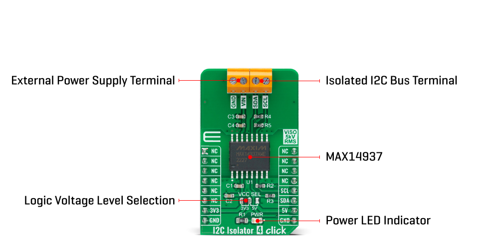
The I2C Isolator 4 Click Board™ also possesses two terminals labelled as VIN and SDA/SCL at the bottom of the Click board™, where VIN represents the B-side power supply of the isolator. At the same time, the other corresponds to the isolated bidirectional logic-bus terminal.
This Click board™ can operate with both 3.3V and 5V logic voltage levels selected via the VCC SEL jumper. This way, it is allowed for both 3.3V and 5V capable MCUs to use the communication lines properly. However, the Click board™ comes equipped with a library containing easy-to-use functions and an example code that can be used, as a reference, for further development.
SPECIFICATIONS
| Type | I2C,Isolators |
| Applications | Can be used for transferring digital signals between circuits with different power domains |
| On-board modules | MAX14937 - two-channel I2C digital isolator from Analog Devices |
| Key Features | Robust galvanic isolation of digital signals, withstands 5kVRMS for 60s, low power consumption, supports I2C clock stretching, glitch-free operation, excellent reliability, long operational life, and more |
| Interface | I2C |
| Compatibility | mikroBUS |
| Click board size | M (42.9 x 25.4 mm) |
| Input Voltage | 3.3V or 5V |
PINOUT DIAGRAM
This table shows how the pinout of the I2C Isolator 4 Click Board™ corresponds to the pinout on the mikroBUS™ socket (the latter shown in the two middle columns).
| Notes | Pin | Pin | Notes | ||||
|---|---|---|---|---|---|---|---|
| NC | 1 | AN | PWM | 16 | NC | ||
| NC | 2 | RST | INT | 15 | NC | ||
| NC | 3 | CS | RX | 14 | NC | ||
| NC | 4 | SCK | TX | 13 | NC | ||
| NC | 5 | MISO | SCL | 12 | SCL | I2C Clock | |
| NC | 6 | MOSI | SDA | 11 | SDA | I2C Data | |
| Power Supply | 3.3V | 7 | 3.3V | 5V | 10 | 5V | Power Supply |
| Ground | GND | 8 | GND | GND | 9 | GND | Ground |
ONBOARD SETTINGS AND INDICATORS
| Label | Name | Default | Description |
|---|---|---|---|
| LD1 | PWR | - | Power LED Indicator |
| JP1 | VCC SEL | Left | Logic Level Voltage Selection 3V3/5V: Left position 3V3, Right position 5V |
I2C ISOLATOR 4 CLICK ELECTRICAL SPECIFICATIONS
| Description | Min | Typ | Max | Unit |
|---|---|---|---|---|
| Supply Voltage | 3.3 | - | 5 | V |
| Maximum Withstand Isolation Voltage | - | - | 5000 | Vrms |
| Maximum Frequency | - | - | 1.7 | MHz |
| Data Rate | - | - | 1.6 | Mbps |
| General Information | |
|---|---|
Part Number (SKU) |
MIKROE-4675
|
Manufacturer |
|
| Physical and Mechanical | |
Weight |
0.02 kg
|
| Other | |
EAN |
8606027386596
|
Frequently Asked Questions
Have a Question?
Be the first to ask a question about this.