


Mikroelektronika d.o.o.
SKU: MIKROE-4658Load Cell 3 Click Board
Load Cell 3 Click Board
Couldn't load pickup availability
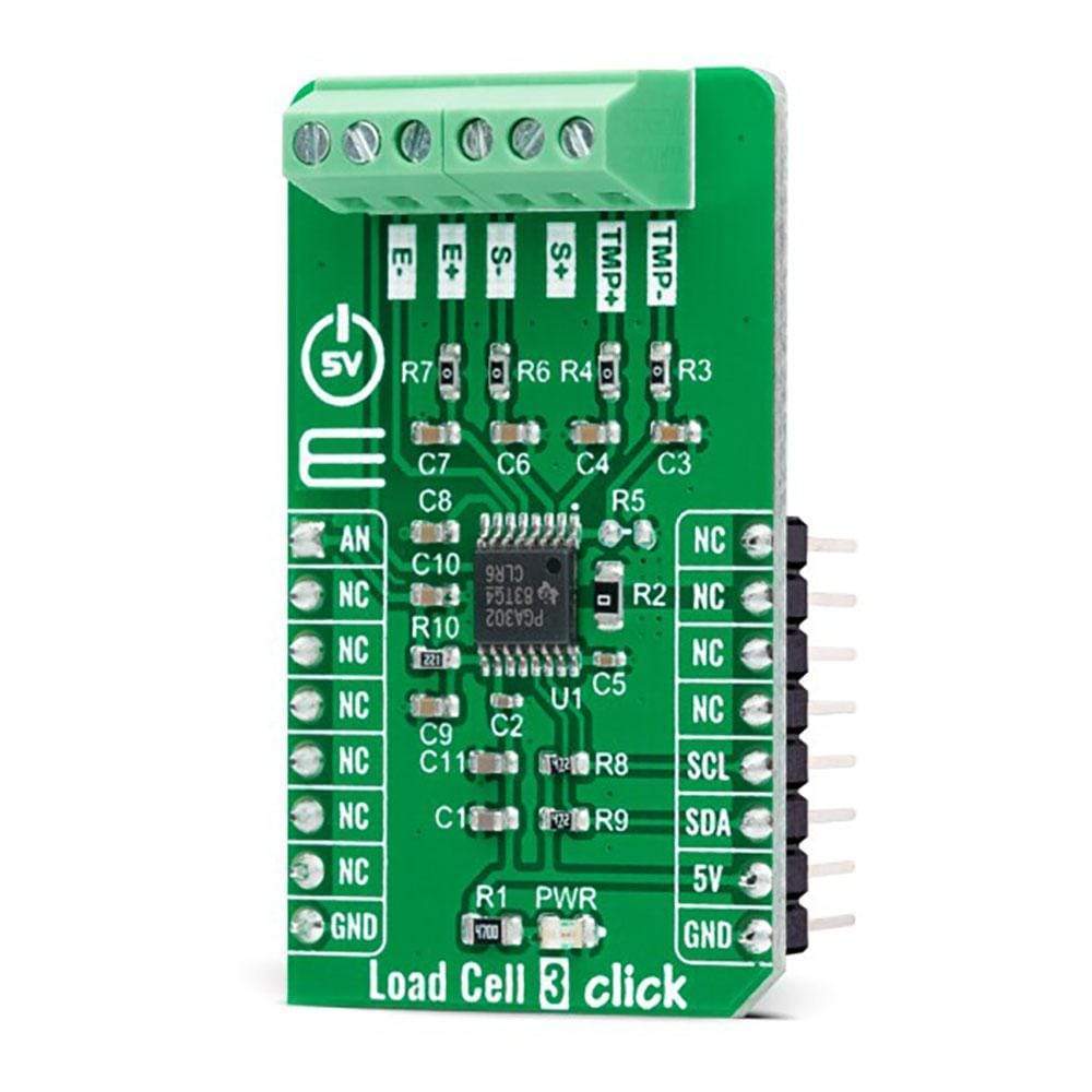
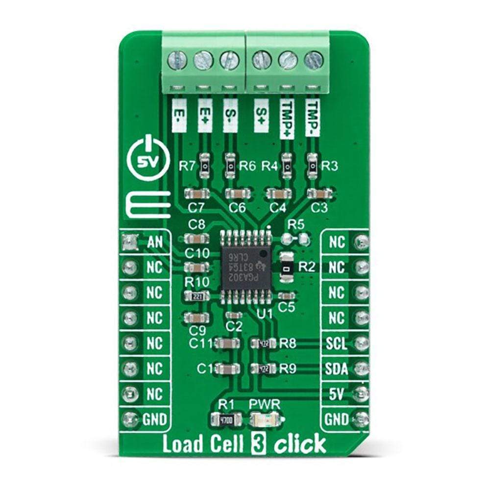
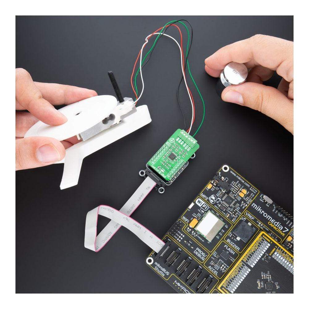
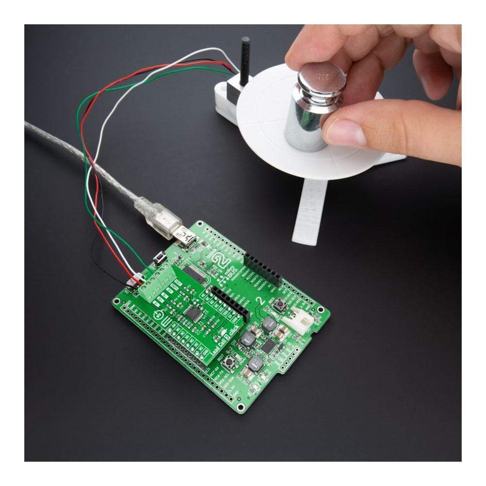
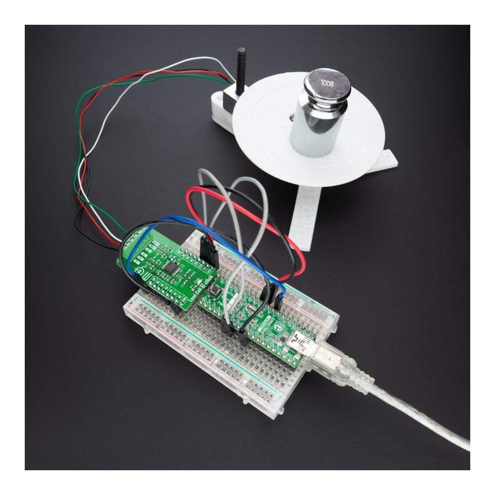
The Load Cell 3 Click Board™ is a compact add-on board that represents a weigh scale solution. This board features the PGA302, a low-drift, low-noise, programmable signal-conditioner device designed for various resistive bridge-sensing applications from Texas Instruments. It creates 2.5V of bridge excitation and a current output source with programmable current output up to 1mA. Two identical analogue front-end (AFE) channels followed by a 16-bit Sigma-Delta ADC are available at the input, where each AFE channel has a dedicated programmable gain amplifier with gain up to 200V/V. It also comes with an on-chip temperature sensor and integrated EEPROM memory for device configuration, calibration, and user data.
The Load Cell 3 Click Board™ has many features that make it a perfect solution for weight scale and force-sensing applications that use strain gauge load cells and other general resistive bridge signal-conditioning applications.
How Does the Load Cell 3 Click Board™ Work?
The Load Cell 3 Click Board™ as its foundation uses the PGA302, a high accuracy, low drift, low noise, low power, and versatile signal conditioner automotive grade-qualified device for resistive bridge pressure and temperature-sensing applications from Texas Instruments. The PGA302 provides bridge excitation voltages of 2.5V. The PGA302 conditions sensing and temperature signals by amplifying and digitizing through the analogue front end chain and performing linearization and temperature compensation. The conditioned signals can be output in analogue form, and, besides that, the signal data can be accessed by an I2C digital interface.

The PGA302 contains two separated analogue-front end (AFE) chains with their gain amplifiers for resistive bridge and temperature sensing inputs. The resistive bridge input AFE chain consists of a programmable gain with eight steps from 1.33V/V to 200V/V. For the temperature-sensing input AFE chain, the PGA302 provides a current source that can source up to 1mA for the optional external temperature sensing available on the on-board terminal labelled with TMP+ and TMP-.
After the ADC decimation filters, the digitalized signals are sent to the linearization and compensation calculation digital signal logic. All required parameters for the linearization algorithm and other user data are stored in the integrated EEPROM memory. At the device's output, a 14-bit DAC is followed by a ratiometric-voltage supply output buffer with a gain of 4 V/V allowing a 0-5V ratiometric voltage system output available on the AN pin on the mikroBUS™ socket.
The Load Cell 3 Click Board™ operates only with a 5V logic voltage level. The board must perform appropriate logic voltage level conversion before use with MCUs with different logic levels. However, the Click board™ comes equipped with a library containing functions and an example code that can be used, as a reference, for further development.
SPECIFICATIONS
| Type | Force |
| Applications | Can be used for weight scale and force-sensing applications that use strain gauge load cells and other general resistive bridge signal-conditioning applications. |
| On-board modules | PGA302 - a programmable signal-conditioner device designed for various resistive bridge-sensing applications from Texas Instruments |
| Key Features | Dual-channel analogue front-end, 16-bit Sigma-Delta ADC, programmable gain up to 200V/V, on-chip temperature sensor, EEPROM memory for device configuration, calibration and user data, and more. |
| Interface | Analog, I2C |
| Compatibility | mikroBUS |
| Click board size | M (42.9 x 25.4 mm) |
| Input Voltage | 5V |
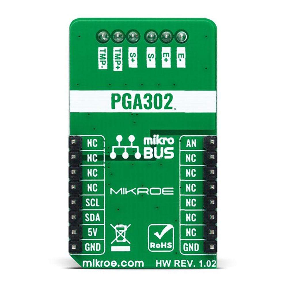
PINOUT DIAGRAM
This table shows how the pinout on Load Cell 3 Click corresponds to the pinout on the mikroBUS™ socket (the latter shown in the two middle columns).
| Notes | Pin | Pin | Notes | ||||
|---|---|---|---|---|---|---|---|
| Analog Signal | AN | 1 | AN | PWM | 16 | NC | |
| NC | 2 | RST | INT | 15 | NC | ||
| NC | 3 | CS | RX | 14 | NC | ||
| NC | 4 | SCK | TX | 13 | NC | ||
| NC | 5 | MISO | SCL | 12 | SCL | I2C Clock | |
| NC | 6 | MOSI | SDA | 11 | SDA | I2C Data | |
| NC | 7 | 3.3V | 5V | 10 | 5V | Power Supply | |
| Ground | GND | 8 | GND | GND | 9 | GND | Ground |
ONBOARD SETTINGS AND INDICATORS
| Label | Name | Default | Description |
|---|---|---|---|
| LD1 | PWR | - | Power LED Indicator |
LOAD CELL 3 CLICK ELECTRICAL SPECIFICATIONS
| Description | Min | Typ | Max | Unit |
|---|---|---|---|---|
| Supply Voltage | - | 5 | - | V |
| ADC Resolution | - | 16 | - | bits |
| Operating Temperature Range | -40 | +25 | +150 | °C |
Software Support
We provide a library for the Load Cell 3 Click Board™ as well as a demo application (example), developed using MikroElektronika compilers. The demo can run on all the main MikroElektronika development boards.
The package can be downloaded/installed directly from NECTO Studio Package Manager(recommended way), downloaded from our LibStock™ or found on Mikroe Github account.
Library Description
This library contains API for Load Cell 3 Click driver.
Key Functions
loadcell3_cfg_setup- Config Object Initialization function.loadcell3_init- Initialization function.loadcell3_default_cfg- Click the Default Configuration function.
Example Description
This library contains an API for the Load Cell 3 Click Board™ driver. The library also includes a function for tare and calibration and weight measurement. This demo application shows an example of weight measurement.
The demo application is composed of two sections :
void application_task ( void ) {
 weight_val = loadcell3_get_weight( &loadcell3, &cell_data );
 log_printf( &logger, " Weight : %.2f grn", weight_val );
 Delay_ms( 1000 );
}
The full application code, and ready to use projects can be installed directly from NECTO Studio Package Manager(recommended way), downloaded from our LibStock™ or found on Mikroe Github account.
Other Mikroe Libraries used in the example:
- MikroSDK.Board
- MikroSDK.Log
- Click.LoadCell3
Additional Notes and Information
Depending on the development board you are using, you may need a USB UART click, USB UART 2 click or RS232 click to connect to your PC, for development systems with no UART to USB interface available on the board. The terminal available in all MikroElektronika compilers, or any other terminal application of your choice, can be used to read the message.
MIKROSDK
The Load Cell 3 Click Board™ is supported with mikroSDK - MikroElektronika Software Development Kit. To ensure proper operation of mikroSDK compliant Click board™ demo applications, mikroSDK should be downloaded from the LibStock and installed for the compiler you are using.
Load Cell 3 Click Board
Frequently Asked Questions
Have a Question?
Be the first to ask a question about this.