


Mikroelektronika d.o.o.
DIGI POT 8 Click Board™
DIGI POT 8 Click Board™
SKU: MIKROE-4596
Couldn't load pickup availability
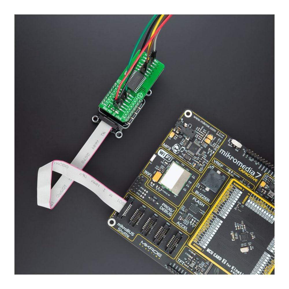
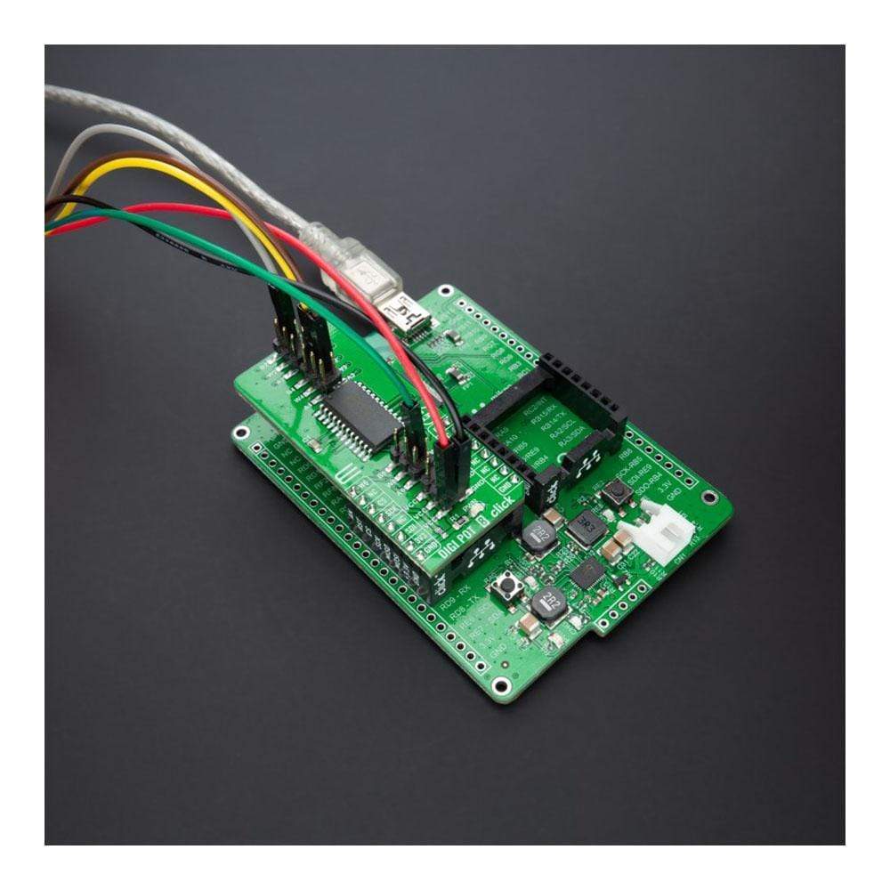
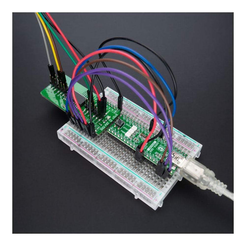
Overview
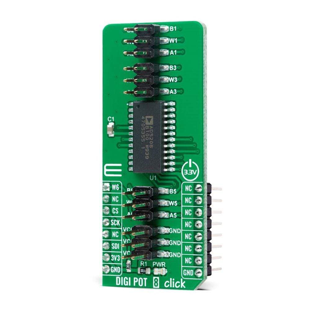
The DIGI POT 8 Click Board™ is a compact add-on board used as a digitally controlled potentiometer. This board features the AD5206, 6-channel 256-position digitally controlled variable resistor device from Analog Devices. Each channel of the AD5206 contains a fixed resistor with a wiper contact that taps the fixed resistor value of 10kΩ, 50kΩ, or 100kΩ at a point determined by a digital code loaded into the SPI-compatible serial-input register. This Click Board™ can be used as mechanical potentiometer replacements, voltage-to-current conversions, gain and offset adjustment, and many other applications.
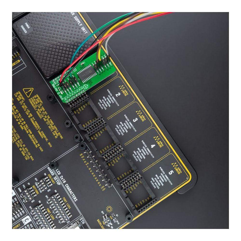
The DIGI POT 8 Click Board™ is supported by a mikroSDK compliant library, which includes functions that simplify software development. This Click Board™ comes as a fully tested product, ready to be used on a system equipped with the mikroBUS™ socket.
Downloads
How Does The Digi Pot 8 Click Board™ Work?
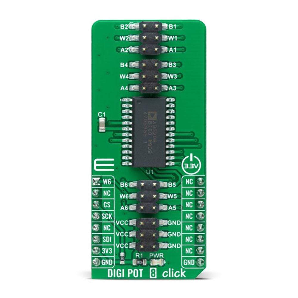
The DIGI Pot 8 Click Board™ as its foundation uses the AD5206, 6-channel 256-position digitally controlled device that performs the same electronic adjustment function as a potentiometer or variable resistor from Analog Devices. Each channel of the AD5206 contains a fixed resistor with a wiper contact that taps the fixed resistor value of 10kΩ, 50kΩ, or 100kΩ at a point determined by a digital code loaded into the SPI-compatible serial-input register. The resistance between the wiper and either endpoint of the fixed resistor varies linearly concerning the digital code transferred into the variable resistor (VR) latch. The AD5206 also has an internal Power-On preset that places the wiper in a preset midscale condition at the Power-On state.

The AD5206 communicates with MCU through the 3-Wire SPI serial interface with a maximum frequency of 10MHz. Each VR has its VR latch that holds its programmed resistance value. These VR latches are updated from an internal serial-to-parallel shift register loaded from a standard 3-wire SPI serial-input digital interface. Eleven data bits make up the data word clocked into the serial input register. The first three bits are decoded to determine which VR latch is loaded with the last eight bits of the data word when the CS pin of the SPI serial interface returns to a logic high state.
In addition to the AD5206 present on the DIGI POT 8, this Click board™ also has four 2x3 male headers. Three of them under the labels of A W and B, with also the appropriate number, represent the corresponding DIGI POT terminal of the AD5206, while the fourth header with the label VCC and GND represents an additional power supply output. Wiper terminal number 6, labeled as W6, also can be used as an auxiliary wiper output, routed to the AN pin of the mikroBUS ™ socket if the wiper back to the mikroBUS™ is required.
This Click board™ can be operated only with a 3.3V logic voltage level. The board must perform appropriate logic voltage level conversion before use with MCUs with different logic levels. However, the Click board™ comes equipped with a library containing functions and an example code that can be used, as a reference, for further development.
SPECIFICATIONS
| Type | Digital potentiometer |
| Applications | Can be used as mechanical potentiometer replacements, voltage-to-current conversions, gain and offset adjustment, and many other applications |
| On-board modules | AD5206 - 6-channel 256-position digitally controlled device that performs the same electronic adjustment function as a potentiometer or variable resistor from Analog Devices |
| Key Features | 256 positions, 6 independently programmable channels, potentiometer replacement, terminal resistance of 10kΩ, 50kΩ, 100kΩ, SPI compatible, and more |
| Interface | Analog |
| Compatibility | mikroBUS |
| Click board size | L (57.15 x 25.4 mm) |
| Input Voltage | 3.3V |
PINOUT DIAGRAM
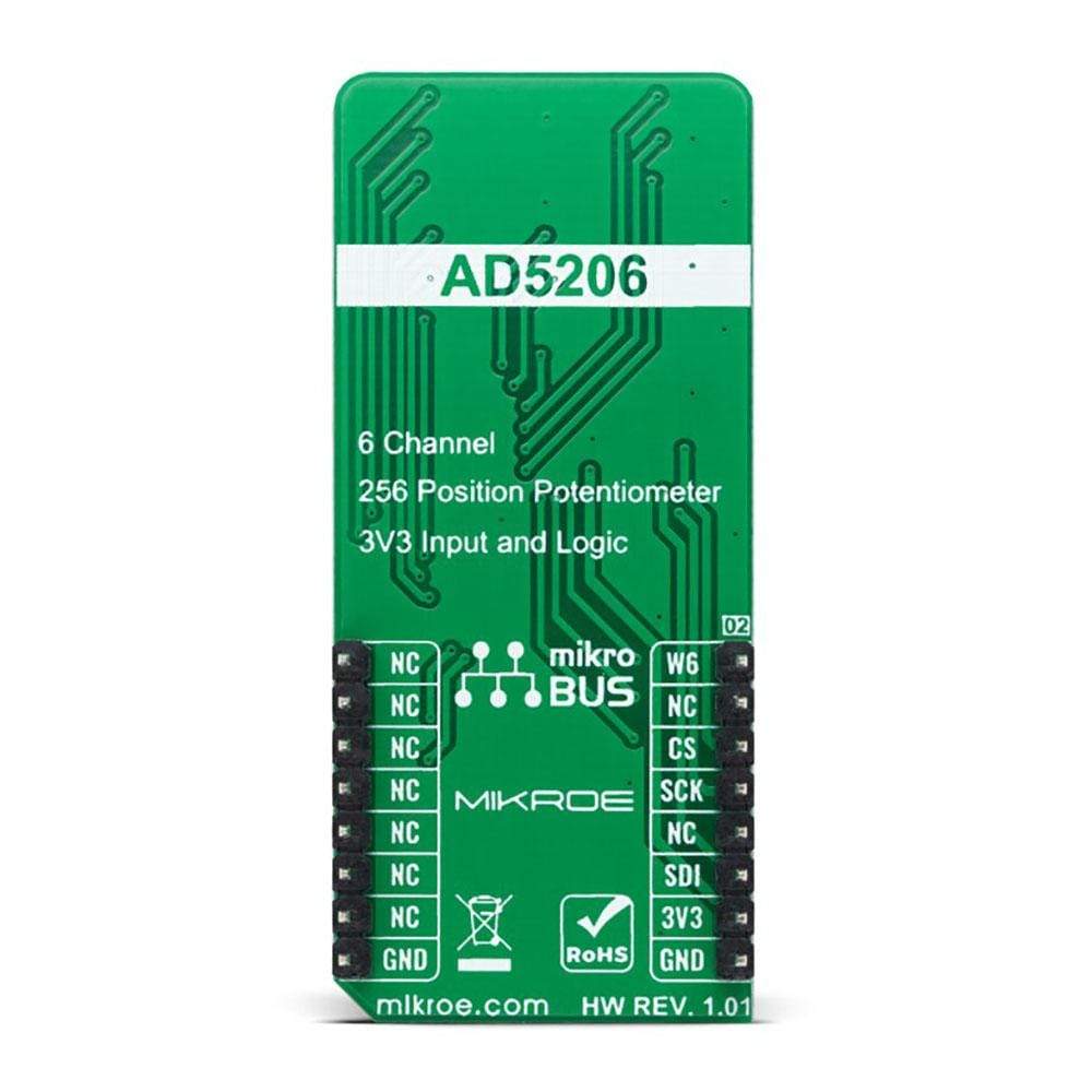
This table shows how the pinout on DIGI POT 8 Click corresponds to the pinout on the mikroBUS™ socket (the latter shown in the two middle columns).
| Notes | Pin |  |
Pin | Notes | |||
|---|---|---|---|---|---|---|---|
| Wiper OUT | AN | 1 | AN | PWM | 16 | NC | |
| NC | 2 | RST | INT | 15 | NC | ||
| SPI Chip Select | CS | 3 | CS | RX | 14 | NC | |
| SPI Clock | SCK | 4 | SCK | TX | 13 | NC | |
| NC | 5 | MISO | SCL | 12 | NC | ||
| SPI Data IN | SDI | 6 | MOSI | SDA | 11 | NC | |
| Power Supply | 3.3V | 7 | 3.3V | 5V | 10 | NC | |
| Ground | GND | 8 | GND | GND | 9 | GND | Ground |
ONBOARD SETTINGS AND INDICATORS
| Label | Name | Default | Description |
|---|---|---|---|
| LD1 | PWR | - | Power LED Indicator |
| J1-J3 | - | Populated | DIGI POT Channel Headers |
| J4 | - | Populated | Power Supply Output Header |
DIGI POT 8 CLICK ELECTRICAL SPECIFICATIONS
| Description | Min | Typ | Max | Unit |
|---|---|---|---|---|
| Supply Voltage | - | 3.3 | - | V |
| Resistance | - | - | 100 | kΩ |
| Number of Taps | - | - | 256 | |
| Operating Temperature Range | -40 | +25 | +85 | °C |
| General Information | |
|---|---|
Part Number (SKU) |
MIKROE-4596
|
Manufacturer |
|
| Physical and Mechanical | |
Weight |
0.02 kg
|
| Other | |
EAN |
8606027382567
|