


Mikroelektronika d.o.o.
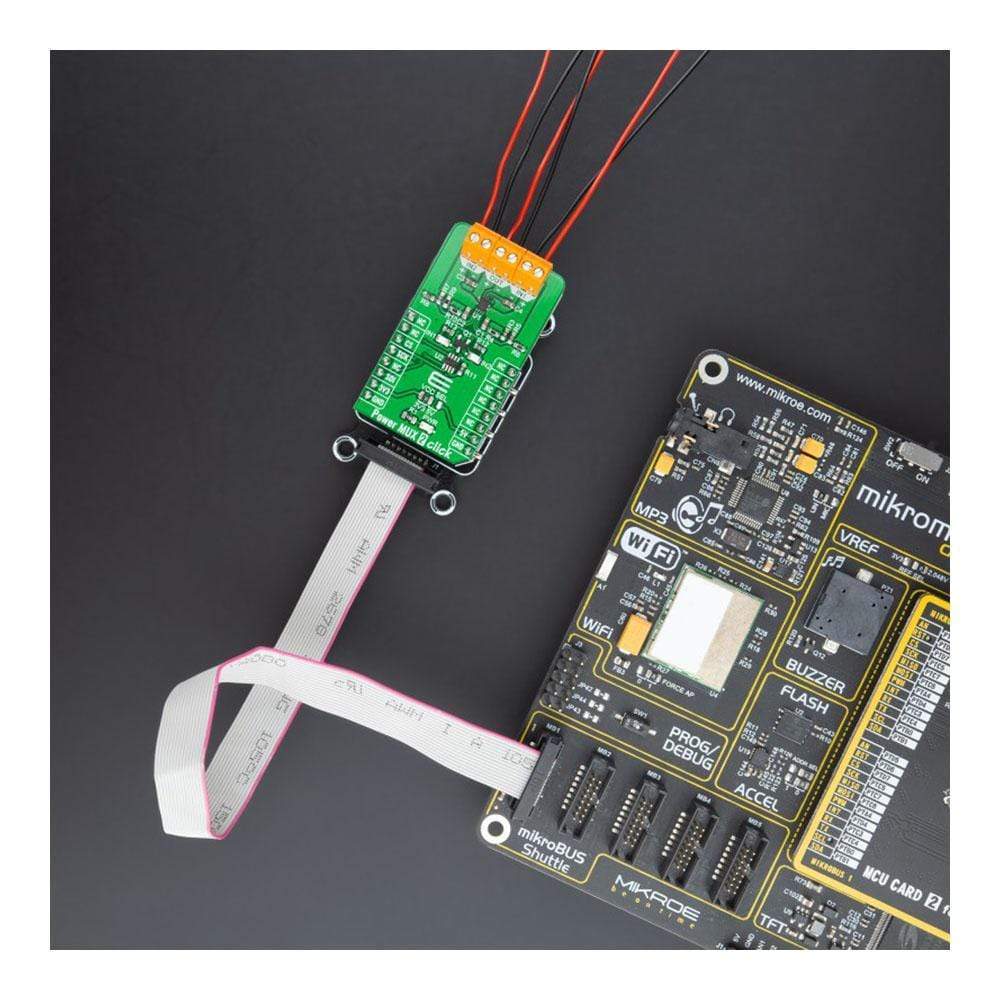
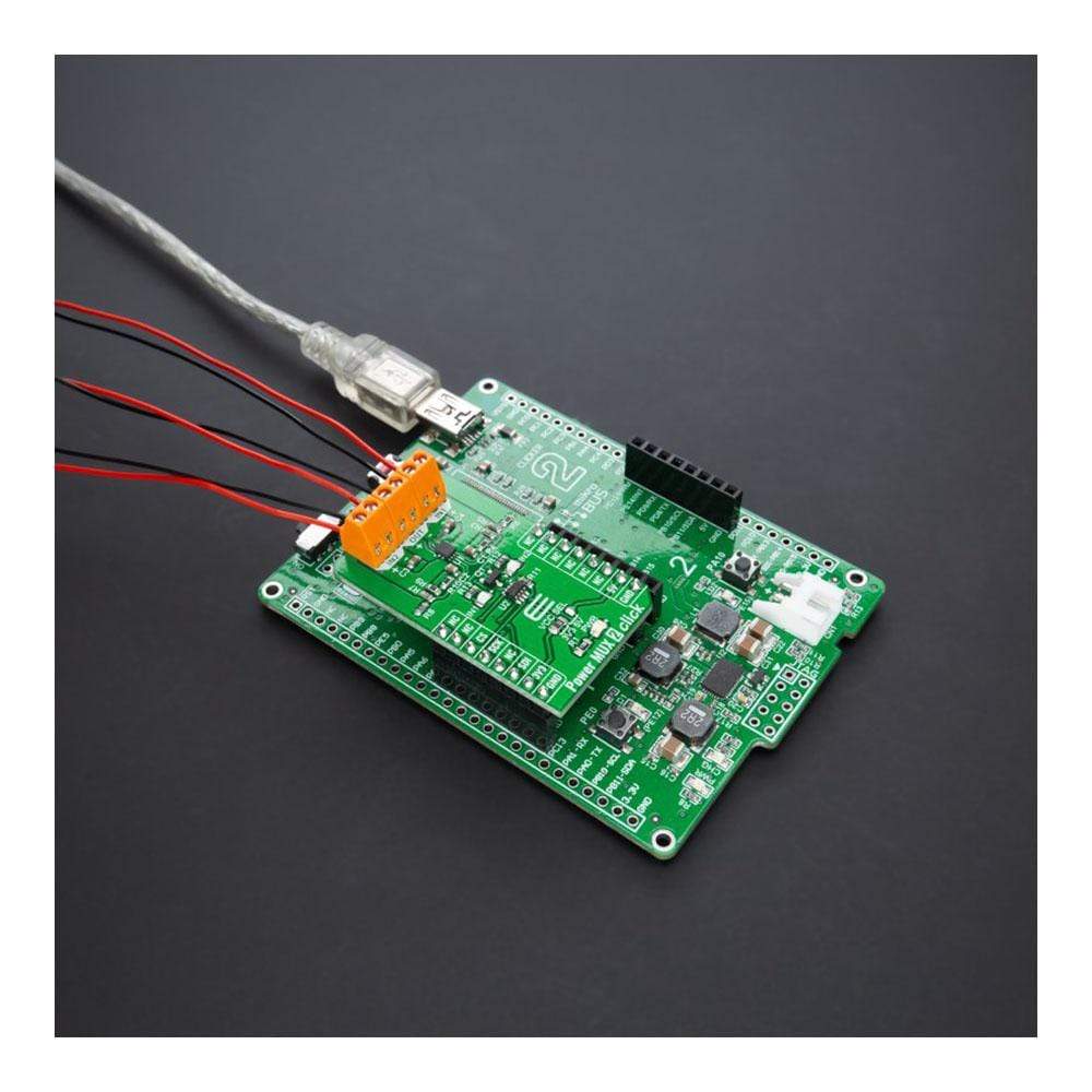
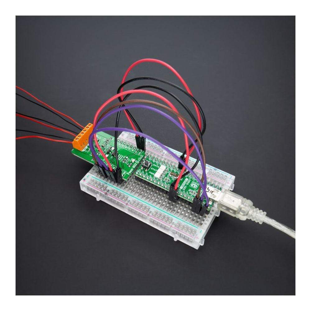
Power MUX 2 Click Board™
Power MUX 2 Click Board™
SKU: MIKROE-4575
Couldn't load pickup availability
Overview
The Power MUX 2 Click Board™ is a compact add-on board with a highly configurable power mux. This board features the TPS2120, a dual-input single-output power multiplexer with an automatic switchover feature from Texas Instruments. This Click Board™ prioritises the main supply when present and quickly switches to auxiliary supply when the main supply drops. During switchover, the voltage drop is controlled to block reverse current before it happens and provide uninterrupted power to the load with minimal hold-up capacitance. This Click Board™ is suitable for backup and standby power applications, input source selection, and various systems having multiple power sources.
The Power MUX 2 Click Board™ is supported by a mikroSDK compliant library, which includes functions that simplify software development. This Click Board™ comes as a thoroughly tested product, ready to be used on a system equipped with the mikroBUS™ socket.
Downloads
How Does The Power MUX 2 Click Board™ Work?
The Power MUX 2 Click Board™ as its foundation uses the TPS2120, a highly configurable power mux with an automatic switchover feature from Texas Instruments. This dual-input single-output power multiplexer prioritizes the main supply of 12V when present and quickly switches to an auxiliary supply of 5 V when the main supply drops. A priority voltage supervisor is used to select an input source. During switchover, the voltage drop is controlled to block reverse current before it happens and provide uninterrupted power to the load with minimal hold-up capacitance.
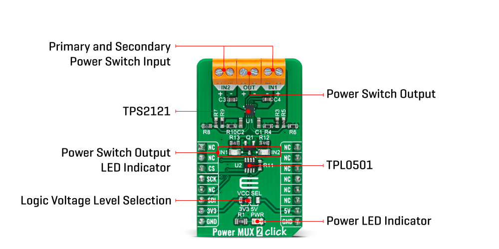
If one of the input power supplies were to fail, the system needs to automatically switchover to a backup power source without interrupting regular operation. When the 12V supply on IN1 drops below 7.6V, the device will automatically switch to the 5V auxiliary supply on IN2. When the 12V supply returns, it will become the output supply again. Furthermore, the voltage drop on the output should be minimal, providing the output with uninterrupted redundant power.
The Power MUX 2 Click Board™ communicates with MCU through the 3-Wire SPI serial interface using the TPL0501, an onboard 256-taps digital potentiometer from Texas Instruments. This way, the TPL0501 serves a current limiter that adjusts the output current of the TPS2120 instead of an external resistor. Current limiting can be used during Startup and switchover to protect against overcurrent events and protect the device during regular operation.
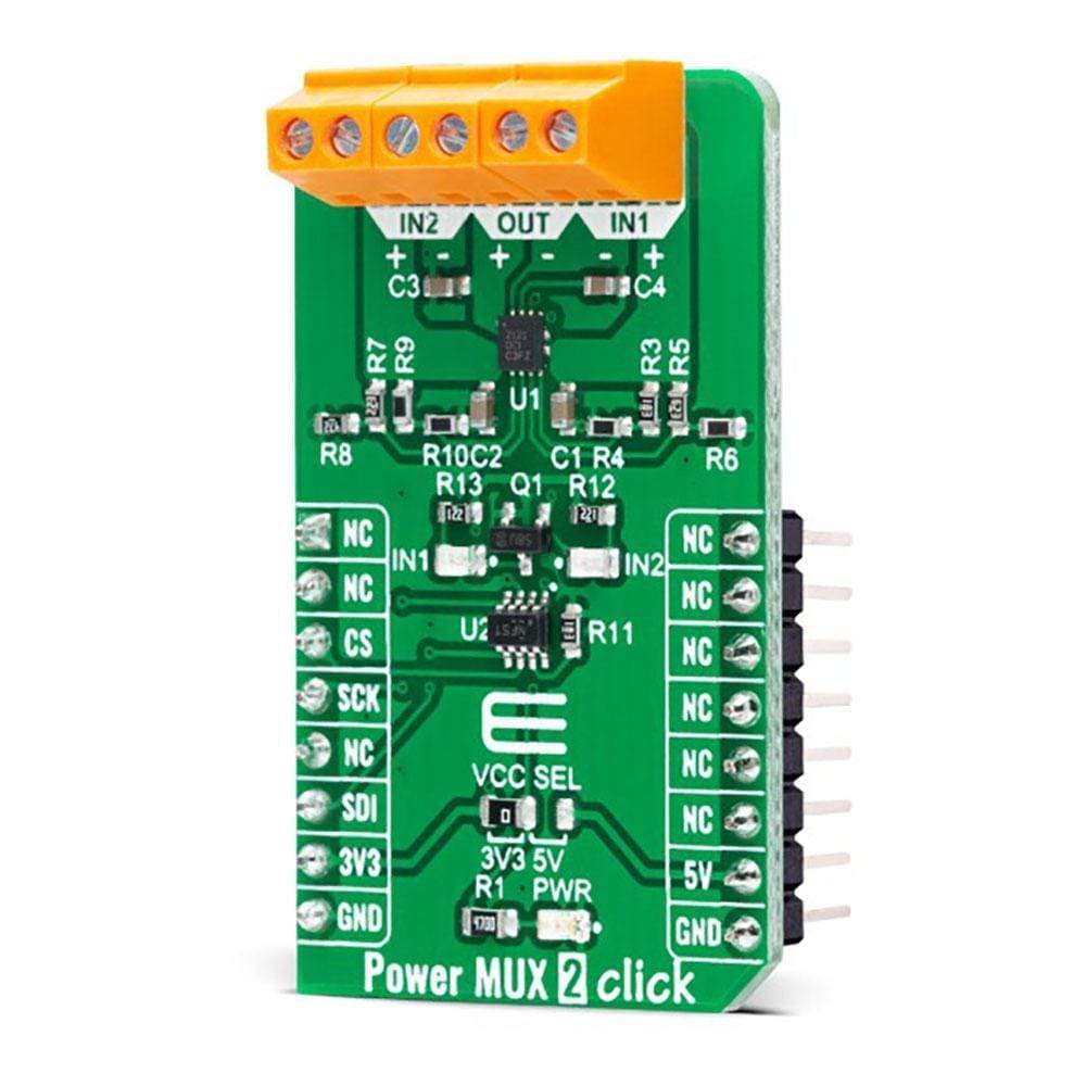
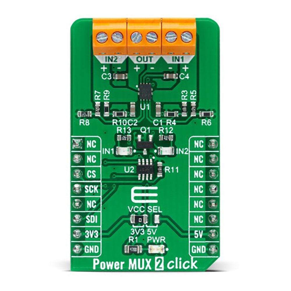
As an additional feature, this Click board™ also has two red LED indicators labelled as IN1 and IN2, which visually indicate to the user the fact which one of the two power supplies, IN1 or IN2, is located on the output more precisely on the output connector of the Click board, labelled as OUT. The Power MUX 2 Click Board™ can operate with both 3.3V and 5V logic voltage levels selected via the VCC SEL jumper. This way, it is allowed for both 3.3V and 5V capable MCUs to properly use the SPI communication lines. However, the Click board™ comes equipped with a library containing easy-to-use functions and an example code that can be used, as a reference, for further development.
SPECIFICATIONS
| Type | Power Switch |
| Applications | Can be used for applications as a backup and standby power, input source selection, and various systems having multiple power sources. |
| On-board modules | TPS2120 - highly configurable power mux with an automatic switchover feature from Texas Instruments TPL0501 - 256-taps digital potentiometer from Texas Instruments |
| Key Features | Low power consumption, automatic switchover, output current limit, uninterrupted power solution, and more. |
| Interface | SPI |
| Compatibility | mikroBUS |
| Click board size | M (42.9 x 25.4 mm) |
| Input Voltage | 3.3V or 5V |
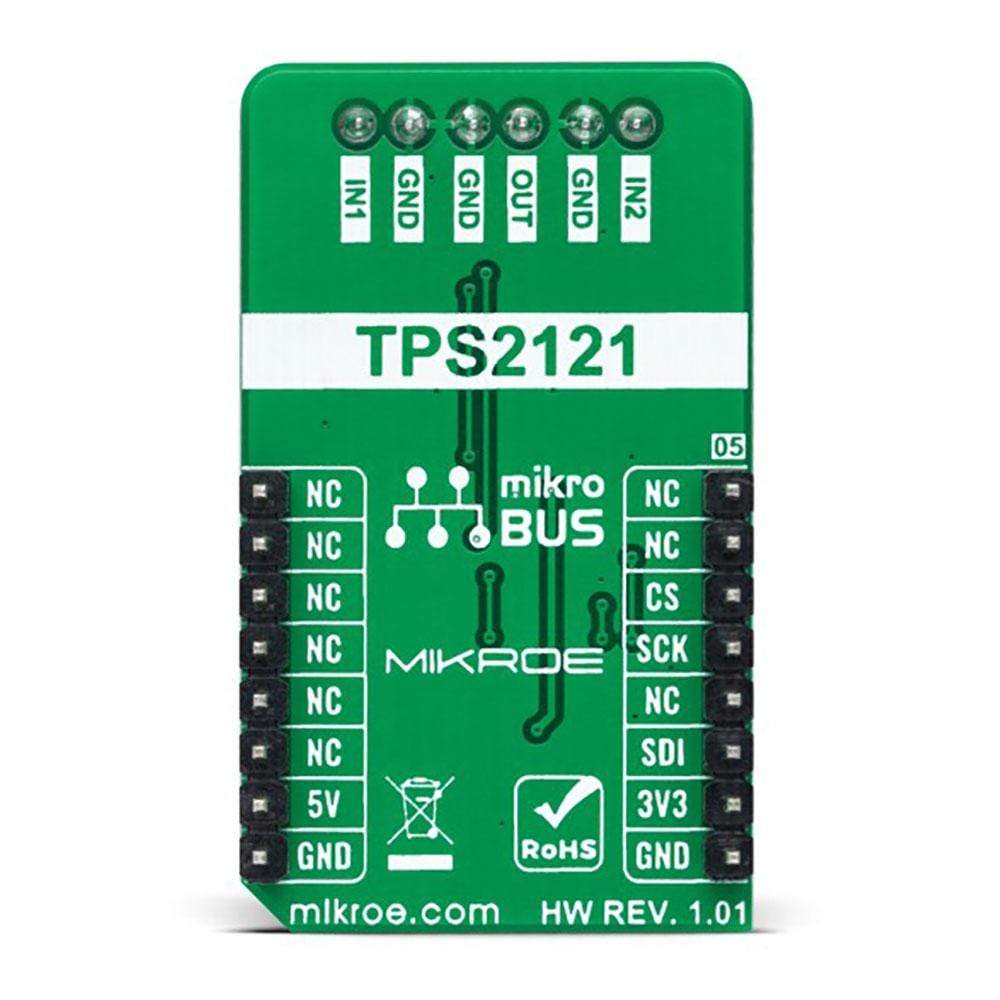
PINOUT DIAGRAM
This table shows how the pinout of the Power MUX 2 Click Board™ corresponds to the pinout on the mikroBUS™ socket (the latter shown in the two middle columns).
| Notes | Pin | Pin | Notes | ||||
|---|---|---|---|---|---|---|---|
| NC | 1 | AN | PWM | 16 | NC | ||
| NC | 2 | RST | INT | 15 | NC | ||
| SPI Chip Select | CS | 3 | CS | RX | 14 | NC | |
| SPI Clock | SCK | 4 | SCK | TX | 13 | NC | |
| NC | 5 | MISO | SCL | 12 | NC | ||
| SPI Data IN | SDI | 6 | MOSI | SDA | 11 | NC | |
| Power Supply | 3.3V | 7 | 3.3V | 5V | 10 | 5V | Power Supply |
| Ground | GND | 8 | GND | GND | 9 | GND | Ground |
ONBOARD SETTINGS AND INDICATORS
| Label | Name | Default | Description |
|---|---|---|---|
| LD1 | PWR | - | Power LED Indicator |
| LD3 | IN1 | - | Primary Power Switch LED Indicator |
| LD2 | IN2 | - | Secondary Power Switch LED Indicator |
| JP1 | VCC SEL | Left | Logic Level Voltage Selection 3V3/5V: Left position 3V3, Right position 5V |
POWER MUX 2 CLICK ELECTRICAL SPECIFICATIONS
| Description | Min | Typ | Max | Unit |
|---|---|---|---|---|
| Supply Voltage VCC | 3.3 | - | 5 | V |
| Supply Voltage IN1 | 7.6 | - | 12 | V |
| Supply Voltage IN2 | - | 5 | - | V |
| Output Voltage OUT | 5 | - | 12 | V |
| Output Current Limit | 1 | - | 4 | A |
| Current Limit Resistance | 18 | - | 100 | kΩ |
| Operating Temperature Range | -40 | +25 | +85 | °C |
| General Information | |
|---|---|
Part Number (SKU) |
MIKROE-4575
|
Manufacturer |
|
| Physical and Mechanical | |
Weight |
0.019 kg
|
| Other | |
EAN |
8606027382246
|
Frequently Asked Questions
Have a Question?
Be the first to ask a question about this.