Overview
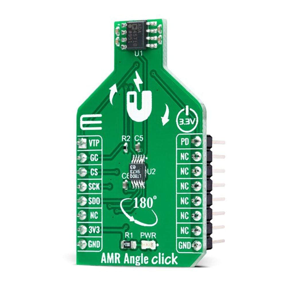
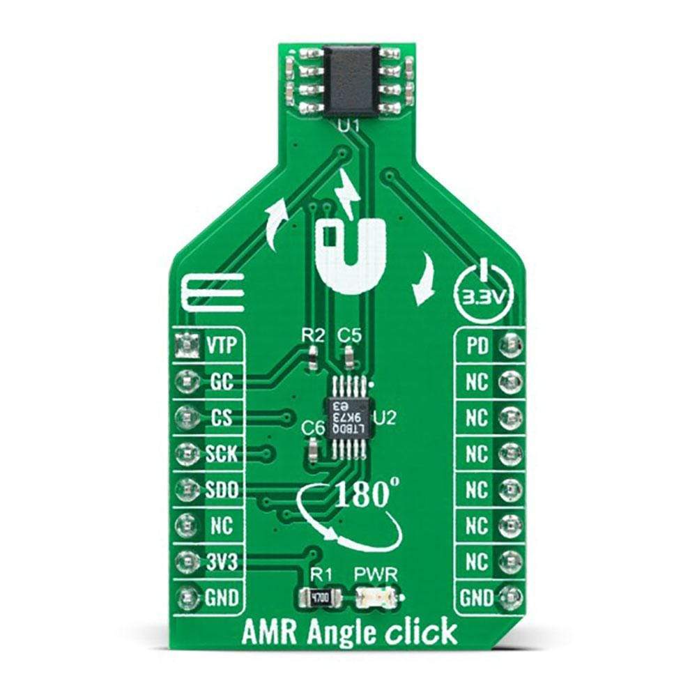
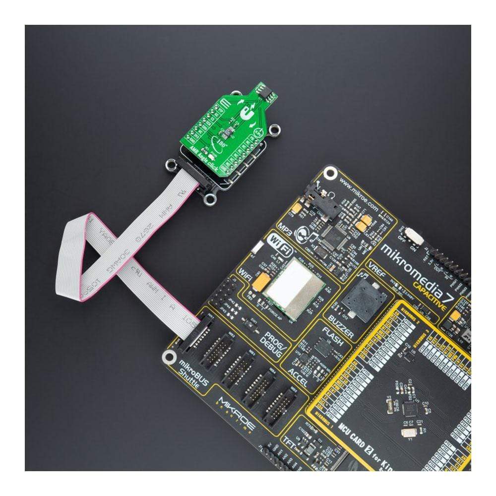
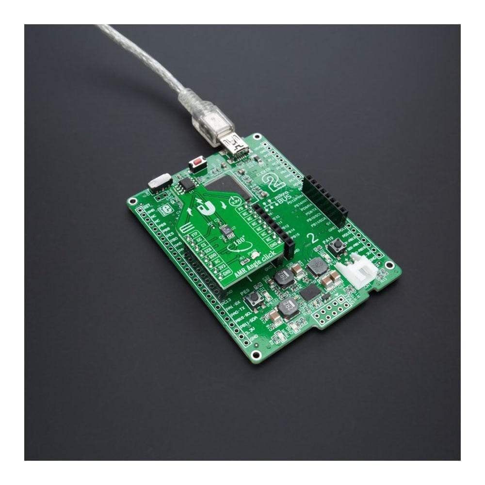
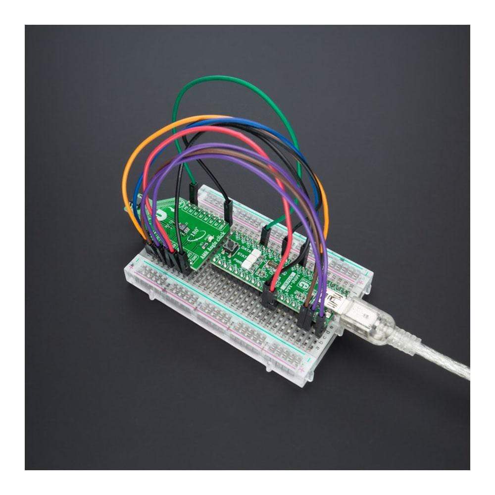
The AMR Angle Click Board™ is a compact add-on board containing an anisotropic magnetoresistive measurement solution ideal for either angle or linear position measurements. This board features the ADA4571, an AMR sensor with clean and amplified cosine and sine output signals related to a rotating magnetic field angle from Analog Devices. It can provide better than 0.2° angular accuracy over 180°, and linear accuracy of 2mil (0.002 inches) over a 0.5-inch range, depending on the size of the used magnet. This Click Board™ is suitable for absolute position measurement (linear and angle), contactless angular measurement and detection, magnetic angular position sensing, actuator control and positioning, and more.
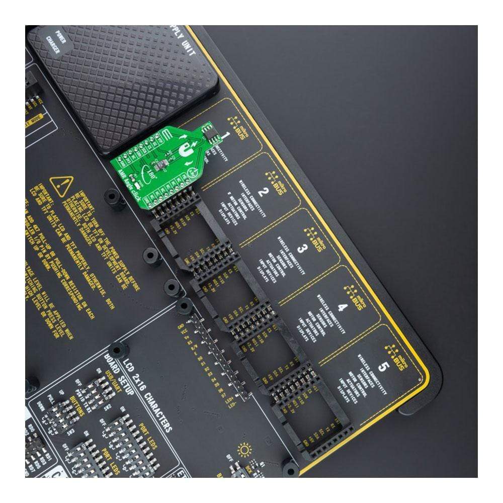
The AMR Angle Click Boiard™ is supported by a mikroSDK compliant library, which includes functions that simplify software development. This Click Board™ comes as a fully tested product, ready to be used on a system equipped with the mikroBUS™ socket.
Downloads
How Does The AMR Angle Click Board™ Work?
The AMR Angle Click Board™, as its foundation, uses the ADA4571, an anisotropic magnetoresistive (AMR) sensor with integrated signal conditioning amplifiers and ADC drivers, as well as a temperature sensor for temperature compensation from Analog Devices. It produces two analogue outputs that indicate the surrounding magnetic field's angular position and consists of two die within one package, an AMR sensor, and a fixed gain instrumentation amplifier, with G=40 nominally. It provides better than 0.2° angular accuracy over 180°, and linear accuracy of 2mil (0.002 inches) over a 0.5-inch range, depending on the used magnet's size.

The ADA4571 contains two Wheatstone bridges, at a relative angle of 45° to one another. A rotating magnetic field in the x-y sensor plane delivers two sinusoidal output signals with the double frequency of the angle between sensor and magnetic field direction. Within a homogeneous field in the x-y plane, the output signals are independent of the physical placement in the z-direction (air gap).
The AMR Angle Click Board™ communicates with MCU through the 3-Wire SPI serial interface using the LTC1407, 12-bit 3MSPS ADC with two 1.5MSPS simultaneously sampled differential inputs from Analog Devices. The LTC1407 samples both channels of the sensor simultaneously using an SPI interface, allowing access to both channels on one data line. Besides, it possesses additional functionality routed on some GPIO pins such as Power-Down mode, Gain control, and temperature monitoring.
The power-down feature labeled as PD and routed on the PWM pin of the mikroBUS™ socket shuts down the device. It sets its outputs to a high impedance to avoid current consumption, while the VTEMP routed on the AN pin can be used for temperature monitoring or calibration purposes. Gain control, labeled as GC and routed on the RST pin of the mikroBUS™ socket, activates by switching this pin to a high level. In this mode, the AMR sensor amplitude outputs are compensated to reduce temperature variation, which results in higher and controlled output voltage levels. It can also be used as a sensor self-diagnostic feature by comparing the sine and cosine amplitude outputs when enabled and disabled, such as radius check.
The AMR Angle Click Board™ can be operated only with a 3.3V logic voltage level. The board must perform appropriate logic voltage level conversion before use with MCUs with different logic levels. However, the Click board™ comes equipped with a library containing functions and an example code that can be used, as a reference, for further development.
SPECIFICATIONS
| Type | Magnetic |
| Applications | Can be used for absolute position measurement (linear and angle), contactless angular measurement and detection, magnetic angular position sensing, actuator control and positioning, and more. |
| On-board modules | ADA4571 - AMR sensor with clean and amplified cosine and sine output signals related to a rotating magnetic field angle from Analog Devices LTC1407 - 12-bit 3MSPS ADC with two 1.5MSPS simultaneously sampled differential inputs from Analog Devices |
| Key Features | High precision 180° angle sensor, maximum angular error of 0.5°, magnetoresistive (MR) bridge temperature compensation mode, fault diagnostic, and more. |
| Interface | SPI |
| Compatibility | mikroBUS |
| Click board size | M (42.9 x 25.4 mm) |
| Input Voltage | 3.3V |
PINOUT DIAGRAM
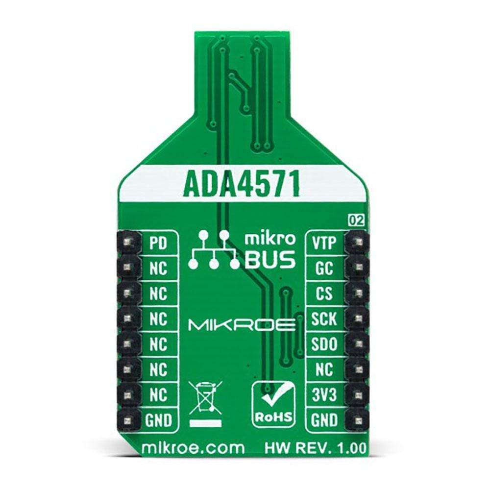
This table shows how the pinout of AMR Angle Click Board™ corresponds to the pinout on the mikroBUS™ socket (the latter shown in the two middle columns).
| Notes | Pin |  |
Pin | Notes | |||
|---|---|---|---|---|---|---|---|
| Temperature Monitoring | VTP | 1 | AN | PWM | 16 | PD | Power-Down Mode |
| Gain Control | GC | 2 | RST | INT | 15 | NC | |
| SPI Chip Select | CS | 3 | CS | RX | 14 | NC | |
| SPI Clock | SCK | 4 | SCK | TX | 13 | NC | |
| SPI Data OUT | SDO | 5 | MISO | SCL | 12 | NC | |
| NC | 6 | MOSI | SDA | 11 | NC | ||
| Power Supply | 3.3V | 7 | 3.3V | 5V | 10 | NC | |
| Ground | GND | 8 | GND | GND | 9 | GND | Ground |
ONBOARD SETTINGS AND INDICATORS
| Label | Name | Default | Description |
|---|---|---|---|
| LD1 | PWR | - | Power LED Indicator |
AMR ANGLE CLICK ELECTRICAL SPECIFICATIONS
| Description | Min | Typ | Max | Unit |
|---|---|---|---|---|
| Supply Voltage | - | 3.3 | - | V |
| Rotation Angle | 0 | - | 180 | degrees |
| Angular Error | - | - | 0.5 | degrees |
| Resolution | 12 | - | - | bits |
| Operating Temperature Range | 0 | +25 | +70 | °C |
| General Information | |
|---|---|
Part Number (SKU) |
MIKROE-4561
|
Manufacturer |
|
| Physical and Mechanical | |
Weight |
0.017 kg
|
| Other | |
Country of Origin |
|
HS Code Customs Tariff code
|
|
EAN |
8606027382185
|
Warranty |
|
Frequently Asked Questions
Have a Question?
Be the first to ask a question about this.


