


Mikroelektronika d.o.o.
SKU: MIKROE-4500ECG GSR Click Board
ECG GSR Click Board
Couldn't load pickup availability
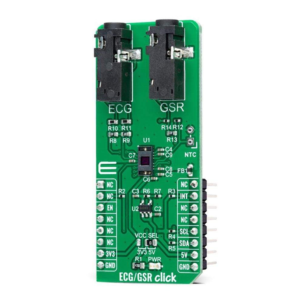
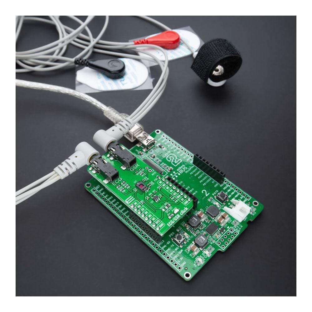
The ECG/GSR Click Board™ is a compact add-on board representing a complete solution for developing ECG and GSR applications. This board features the AS7030B, a vital sign sensor based on Photoplethysmography (PPG) and Electrocardiogram (ECG) operations from AMS-AG. This vital-sign sensor features a low noise analogue front end, a single device integrated optical solution, a synchronous demodulator, and skin temperature and resistivity measurements by providing an interface to external NTC. This Click Board™ is suitable for remote medical diagnostic equipment applications, such as disposable patches for blood oxygen saturation (SpO2) and electrocardiogram (ECG) measurement.
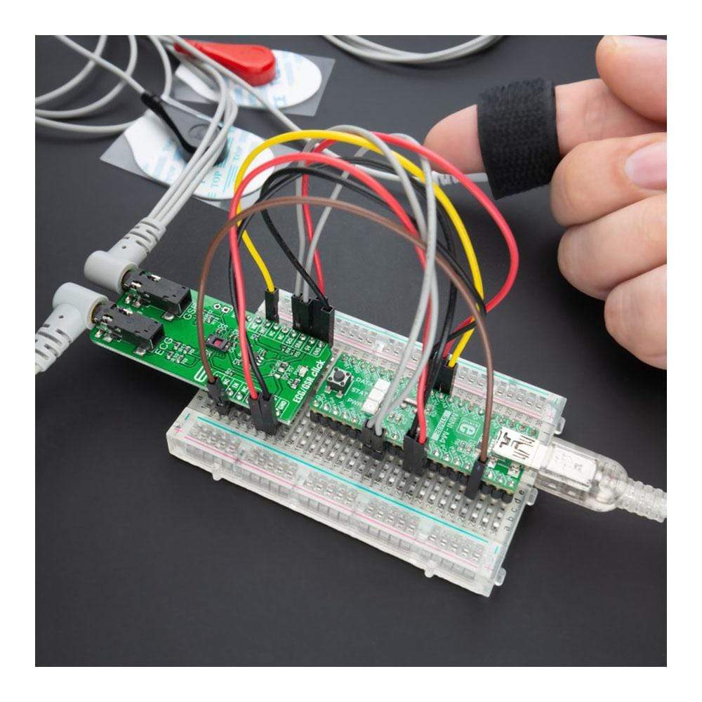
The ECG/GSR Click Board™ is supported by a mikroSDK compliant library, which includes functions that simplify software development. This Click Board™ comes as a thoroughly tested product, ready to be used on a system equipped with the mikroBUS™ socket.
NOTE: the ECG/GSR Click Board™ is a development and prototyping tool. It is not intended to be used for patients' medical treatment and should not be used to diagnose or treat any conditions.

How Does The ECG/GSR Click Board™ Work?
The ECG/GSR Click Board™ as its foundation uses the AS7030B, a vital sign sensor based on Photoplethysmography (PPG) and Electrocardiogram (ECG) operations from AMS-AG. These two popular methods are suitable for heart rate monitoring (HRM) and heart rate variability (HRV), which measure the pulse rate by sampling light modulated by blood vessels that expand and contract as blood pulses through them. The ECG is the reference for any measurement of the bio-potential generated by the heart.
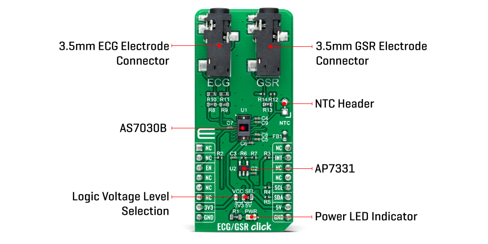
This vital sign sensor features a low noise analogue front end, a single device integrated optical solution, and a synchronous demodulator. It consists of two 527nm green LEDs and one 940nm IR LED. The built-in infrared emitter and dedicated photodiode enable easy integration of proximity function. Besides the HRM and SpO2, the AS7030B is an optical measurement system for GSR (galvanic skin resistivity) and skin temperature obtained via an external temperature sensor connected to an onboard header labelled NTC.
The ECG/GSR Click Board™ communicates with MCU using the standard I2C 2-Wire interface that supports Standard-Mode (100 kHz) and Fast-Mode (400 kHz) operation. Also, it uses two additional pins, the INT pin of the mikroBUS™ socket, used as an interrupt, and the EN pin, routed on the CS pin of the mikroBUS™ socket, used to put the AS7030B into Normal operation mode or in a Shutdown. The AS7030B does not require a specific Power-Up sequence but requires a supply voltage of 3.8V to work correctly. Therefore, the Click board™ uses a low dropout linear regulator AP7331 from Diodes Incorporated, providing a 3.8V out of 5V mikroBUS™ rail.
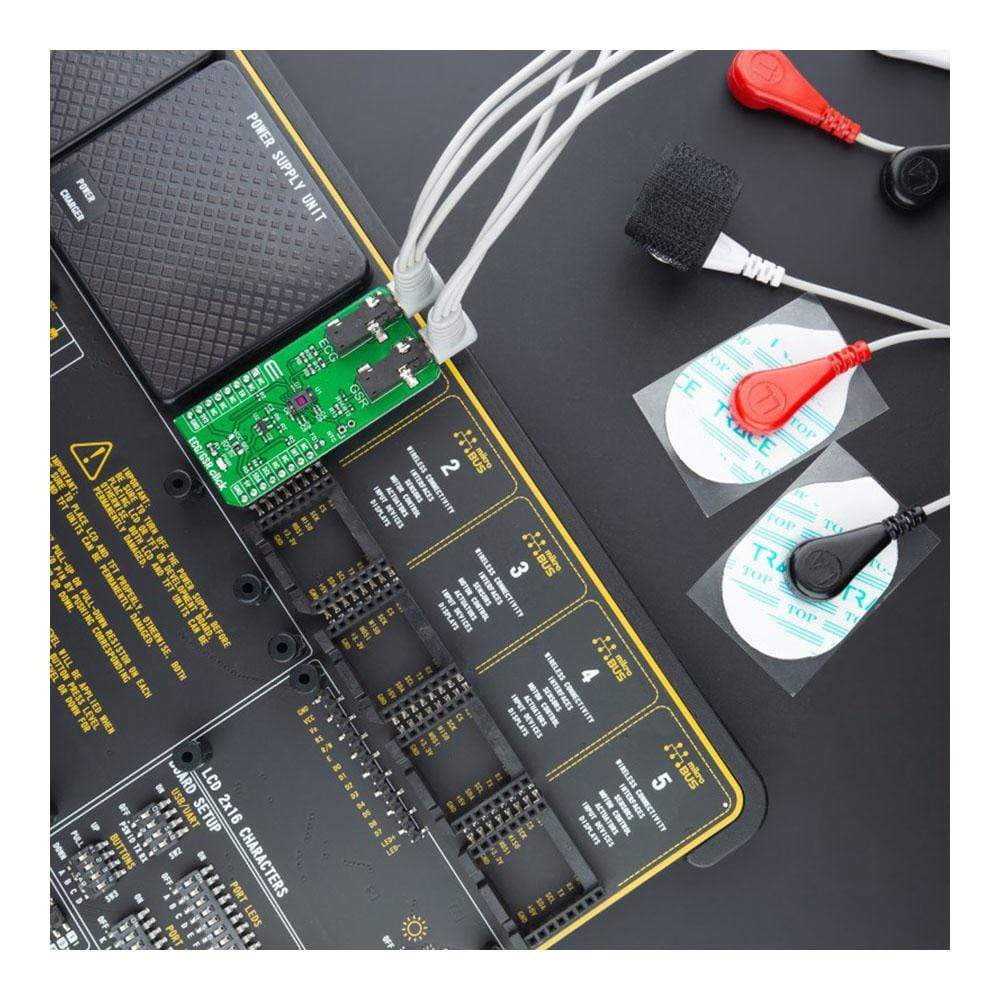
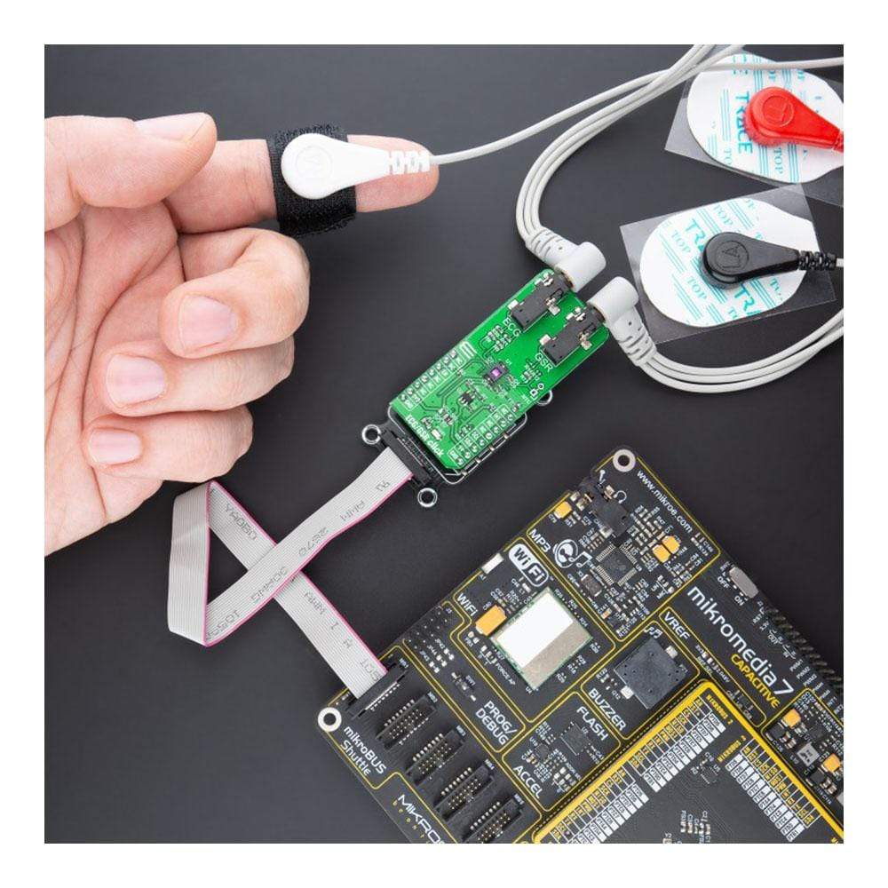
The ECG/GSR Click Board™ consists of two input channels routed to the 3.5mm jack connectors labelled as ECG and GSR, to which a 1m long ECG/EMG cable connects the electrodes to the appropriate Click board™ securely. The two electrode holders consist of a metal piece with a dent in the middle that perfectly fits the rivets on the electrodes. The contact with the measurement Click board™ remains good and secure, while mounting the cable's electrodes is simple and easy.
The ECG/GSR Click Board™ can operate with both 3.3V and 5V logic voltage levels selected via the VCC SEL jumper. This way, it is allowed for both 3.3V and 5V capable MCUs to use the I2C communication lines properly. However, the Click board™ comes equipped with a library containing easy-to-use functions and an example code that can be used, as a reference, for further development.
SPECIFICATIONS
| Type | Biometrics |
| Applications | Can be used for remote medical diagnostic equipment applications, such as disposable patches for blood oxygen saturation (SpO2) and electrocardiogram (ECG) measurement. |
| On-board modules | AS7030B - vital sign sensor based on Photoplethysmography (PPG) and Electrocardiogram (ECG) operations from AMS-AG |
| Key Features | The low-noise analogue front end, synchronised PPG, ECG and GSR acquisition, blood pressure measurements, good HRM quality, temperature sensing using NTC, long operating period, and more. |
| Interface | I2C |
| Compatibility | mikroBUS |
| Click board size | L (57.15 x 25.4 mm) |
| Input Voltage | 3.3V or 5V |
PINOUT DIAGRAM
This table shows how the pinout of the ECG/GSR Click Board™ corresponds to the pinout on the mikroBUS™ socket (the latter shown in the two middle columns).
| Notes | Pin | Pin | Notes | ||||
|---|---|---|---|---|---|---|---|
| NC | 1 | AN | PWM | 16 | NC | ||
| NC | 2 | RST | INT | 15 | INT | Interrupt | |
| Enable | EN | 3 | CS | RX | 14 | NC | |
| NC | 4 | SCK | TX | 13 | NC | ||
| NC | 5 | MISO | SCL | 12 | SCL | I2C Clock | |
| NC | 6 | MOSI | SDA | 11 | SDA | I2C Data | |
| Power Supply | 3.3V | 7 | 3.3V | 5V | 10 | 5V | Power Supply |
| Ground | GND | 8 | GND | GND | 9 | GND | Ground |
ONBOARD SETTINGS AND INDICATORS
| Label | Name | Default | Description |
|---|---|---|---|
| LD1 | PWR | - | Power LED Indicator |
| JP1 | VCC SEL | Left | Logic Level Voltage Selection 3V3/5V: Left position 3V3, Right position 5V |
| J1 | NTC | Unpopulated | External Temperature Sensor Header |
ECG/GSR CLICK ELECTRICAL SPECIFICATION
| Description | Min | Typ | Max | Unit |
|---|---|---|---|---|
| Supply Voltage | 3.3 | - | 5 | V |
| Green LED Wavelength | - | 527 | - | nm |
| IR LED Wavelength | - | 940 | - | nm |
| ADC Resolution | 14 | - | - | bit |
| Relative Accuracy | -8 | - | 8 | LSB |
| Conversion Rate | - | - | 50 | ksps |
| Operating Temperature Range | -30 | +25 | +70 | °C |
Software Support
We provide a library for the ECG/GSR Click Board™ and a demo application (example), developed using MikroElektronika compilers. The demo can run on all the main MikroElektronika development boards.
The package can be downloaded/installed directly from compilers IDE(recommended way), downloaded from our LibStock, or found on the mikroE Github account.
Library Description
This library contains an API for the ECG/GSR Click Board™ driver.
Key Functions
void ecg_gsr_cfg_setup ( ecg_gsr_cfg_t *cfg );- Config Object Initialization function.ecg_gsr_err_t ecg_gsr_init ( ecg_gsr_t *ctx, ecg_gsr_cfg_t *cfg );- Initialization function.void ecg_gsr_default_cfg ( ecg_gsr_t *ctx );- Click Default Configuration function.
Example Description
The ECG/GSR Click Board™ is made for PPG, ECG and GSR, equipped with ultra-low power, multi-channel, integrated biopotential AFE and EFE.
ecg_gsr_err_t application_task( void )
{
    // ------------------------------------------------------------
    // Check the presence of the ECG GSR Click by reading device ID.
    // ------------------------------------------------------------
    ecg_gsr_read_dev_id(&ecg_gsr, ECG_GSR_ID_REG, &dev_id , 1);

    if ( dev_id != ECG_GSR_DEV_ID )
    {
        return ecg_gsr_init_error;
    }

    // ------------------------------------------------------------
    // Enable desired functionality of the ECG GSR Click.
    // ------------------------------------------------------------
    if ( ecg_gsr_cfg.click_functionality == DEFAULT_ECG_GSR_CLICK_FUNCTIONALITY )
    {
        ecg_gsr_get_oxygen_saturation();
    } else if ( ecg_gsr_cfg.click_functionality == ENABLE_HEARTRATE_FUNCTIONALITY )
    {
        ecg_gsr_get_heartrate();
    } else if ( ecg_gsr_cfg.click_functionality == ENABLE_GALVANIC_SKIN_RESPONSE_FUNCTIONALITY )
    {
        ecg_gsr_get_galvanic_skin_response();
    } else
    {
        return ecg_gsr_init_error;
    }

    return ecg_gsr_ok;
}
The complete application code and ready-to-use projects can be installed directly from compilers IDE(recommended) or found on the LibStock page or MikroE GitHub account.
Other mikroE Libraries used in the example:
- MikroSDK.Board
- MikroSDK.Log
- Click.ECG_GSR
Additional Notes and Information
Depending on the development board you are using, you may need USB UART Click Board™, USB UART 2 Click Board™ or RS232 Click Board™ to connect to your PC, for development systems with no UART to USB interface available on the board. The terminal available in all MikroElektronika compilers, or any other terminal application of your choice, can be used to read the message.
MIKROSDK
The ECG/GSR Click Board™ is supported with mikroSDK - MikroElektronika Software Development Kit. To ensure proper operation of mikroSDK compliant Click board™ demo applications, mikroSDK should be downloaded from the LibStock and installed for the compiler you are using.
ECG GSR Click Board
Frequently Asked Questions
Have a Question?
Be the first to ask a question about this.