


Mikroelektronika d.o.o.
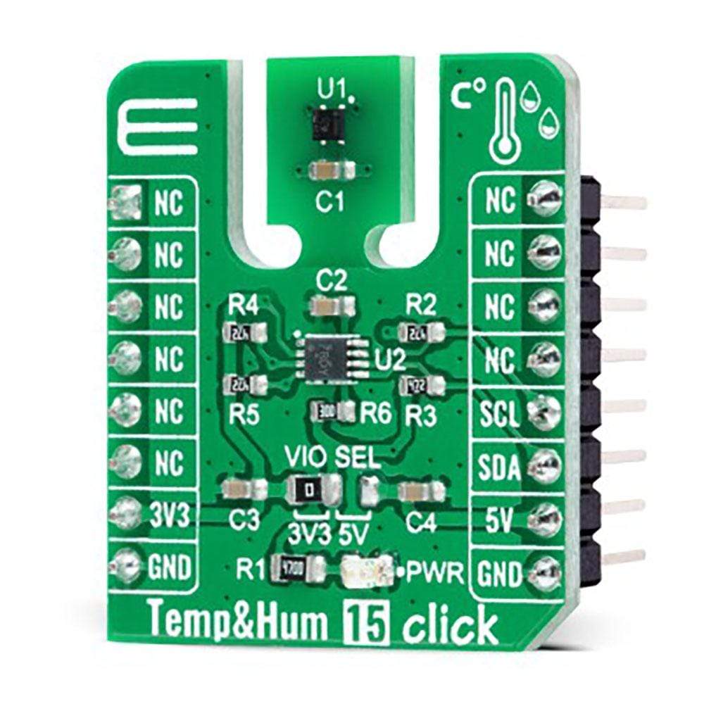
Temp&Hum 15 Click Board™
Temp&Hum 15 Click Board™
SKU: MIKROE-4496
Couldn't load pickup availability
Overview
The Temp&Hum 15 Click Board™ is a compact add-on board that contains the 4th generation of best-in-class SHT humidity sensing solution from Sensirion. This board features the SHT40, a high-accuracy ultra-low-power 16-bit relative humidity, and a temperature sensor. It provides constant temperature accuracy, up to 0.1°C, and shows the best performance when operated within the recommended average temperature and humidity range of 5-60°C and 20-80%RH. The fully calibrated sensor offers linearized digital output, NIST traceability, and I2C Fast Mode Plus. It is reflow solderable and operational in condensing environments. This Click Board™ is an ideal solution for various temperature and humidity-related applications.
The Temp&Hum 15 Click is supported by a mikroSDK compliant library, which includes functions that simplify software development. This Click Board™ comes as a fully tested product, ready to be used on a system equipped with the mikroBUS™ socket.
Downloads
How Does the Temp & Hum 15 Click Board™ Work?
The Temp & Hum 15 Click Board™ as its foundation uses the SHT40, high-accuracy ultra-low-power 16-bit relative humidity and temperature sensor from Sensirion. The SHT40 builds on a wholly new and optimized CMOS chip that offers reduced power consumption and improved accuracy specifications. It provides a fully calibrated digital I2C Fast Mode Plus interface for the fastest data transfer. It covers extended operating humidity and temperature ranges from 0 to 100%RH and from -40°C to 125°C with accuracies of ±1.8%RH and ±0.2°C. The SHT40 also has a power-trimmed internal heater which can be used at three heating levels enabling sensor operation in demanding environments.

![]()
The sensor shows the best performance when operated within the recommended average temperature and humidity range of 5-60°C and 20-80%RH. Long-term exposure to conditions outside recommended normal range, especially at high relative humidity, may temporarily offset the RH signal. After returning to the recommended average temperature and humidity range, the sensor will recover to within specifications by itself.
The Temp&Hum 15 Click Board™ communicates with MCU using the standard I2C 2-Wire interface. Since the sensor for operation requires a 3.3V logic voltage level only, this Click board™ also features the PCA9306 voltage-level translator from Texas Instruments. The I2C interface bus lines are routed to the dual bidirectional voltage-level translator, allowing this Click board™ to work with both 3.3V and 5V MCUs properly.
The Temp&Hum 15 Click Board™ can operate with both 3.3V and 5V logic voltage levels selected via the VIO SEL jumper. This way, it is allowed for both 3.3V and 5V capable MCUs to use the I2C communication lines properly. However, the Click board™ comes equipped with a library that contains easy-to-use functions and an example code that can be used, as a reference, for further development.
SPECIFICATIONS
| Type | Temperature & humidity |
| Applications | Can be used in various temperature and humidity-related applications |
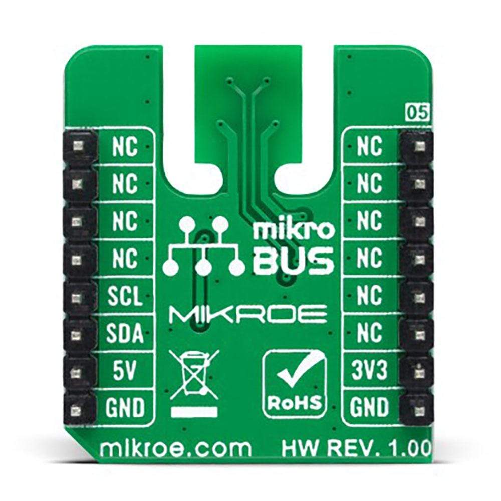
PINOUT DIAGRAM
This table shows how the pinout on Temp&Hum 15 Click corresponds to the pinout on the mikroBUS™ socket (the latter shown in the two middle columns).
| Notes | Pin |
|
Pin | Notes | |||
|---|---|---|---|---|---|---|---|
| NC | 1 | AN | PWM | 16 | NC | ||
| NC | 2 | RST | INT | 15 | NC | ||
| NC | 3 | CS | RX | 14 | NC | ||
| NC | 4 | SCK | TX | 13 | NC | ||
| NC | 5 | MISO | SCL | 12 | SCL | I2C Clock | |
| NC | 6 | MOSI | SDA | 11 | SDA | I2C Data | |
| Power Supply | 3.3V | 7 | 3.3V | 5V | 10 | 5V | Power Supply |
| Ground | GND | 8 | GND | GND | 9 | GND | Ground |
ONBOARD SETTINGS AND INDICATORS
| Label | Name | Default | Description |
|---|---|---|---|
| LD1 | PWR | - | Power LED Indicator |
| JP1 | VIO SEL | Left | Logic Level Voltage Selection 3V3/5V: Left position 3V3, Right position 5V |
TEMP&HUM 15 CLICK ELECTRICAL SPECIFICATIONS
| Description | Min | Typ | Max | Unit |
|---|---|---|---|---|
| Supply Voltage | 3.3 | - | 5 | V |
| Temperature Accuracy | - | ±0.2 | - | °C |
| Relative Humidity Accuracy | - | ±1.8 | - | %RH |
| Resolution | - | 0.01 | - | %RH |
| Operating Humidity Range | 0 | - | 100 | %RH |
| Operating Temperature Range | -40 | +25 | +125 | °C |
| General Information | |
|---|---|
Part Number (SKU) |
MIKROE-4496
|
Manufacturer |
|
| Physical and Mechanical | |
Weight |
0.016 kg
|
| Other | |
EAN |
8606027381881
|
Frequently Asked Questions
Have a Question?
Be the first to ask a question about this.