


Mikroelektronika d.o.o.
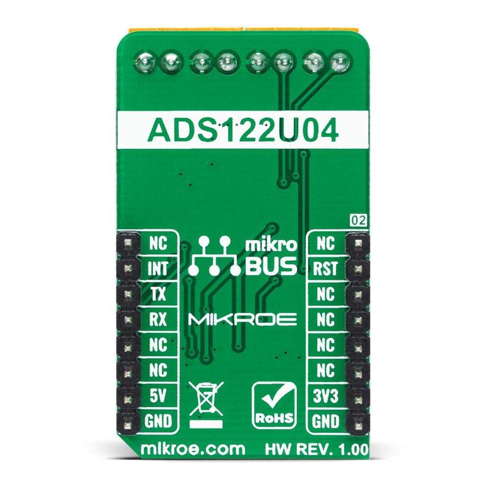
ADC 10 Click Board™
ADC 10 Click Board™
SKU: MIKROE-4488
Couldn't load pickup availability


Key Features
Overview
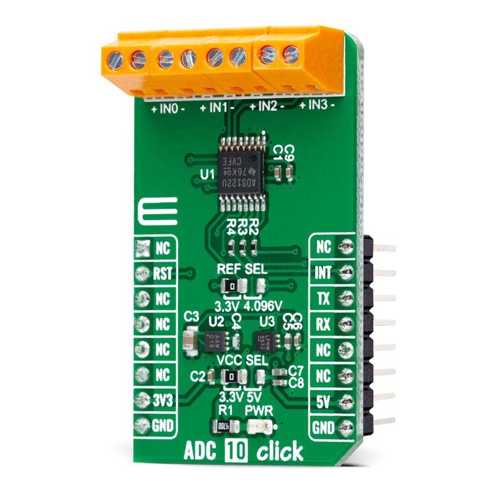
Looking for a high-performance data converter? Look no further than the ADC 10 Click Board™! This compact add-on board features the ADS122U04, a 24-bit precision ΔΣ analogue-to-digital converter with UART compatible interface from Texas Instruments. With its flexible input multiplexer, a programmable gain amplifier, programmable excitation current sources, voltage reference, oscillator, and temperature sensor, the ADS122U04 is capable of conversions at data rates of up to 2000 samples-per-second with single-cycle settling. It's perfect for measuring small sensor signals such as RTDs, thermocouples, thermistors, and resistive bridge sensors.
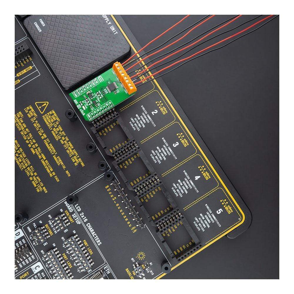
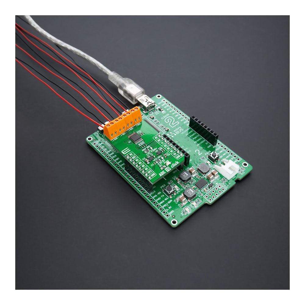
The ADC 10 Click Board™ is easy to use, thanks to its mikroSDK-compliant library and fully tested design. It's ready to be used on any system equipped with a mikroBUS™ socket, making it a convenient and reliable choice for your data conversion needs. Don't miss out on this opportunity to improve your accuracy and performance - get your ADC 10 Click Board™ today!
Downloads
How Does The ADC 10 Click Board™ work?
The ADC 10 Click Board™ is based on the ADS122U04, a 24-bit precision ΔΣ analogue-to-digital converter with UART compatible interface from Texas Instruments. In addition to the ΔΣ ADC and single-cycle settling digital filter, the ADS122U04 offers a low-noise, high input impedance, programmable gain amplifier up to 128, an internal 2.048V voltage reference, and a clock oscillator. It also integrates a highly linear and accurate temperature sensor, and two matched programmable current sources for sensor excitation. The ADS122U04 is fully configured through five registers through the UART interface and can perform conversions at data rates up to 2000 samples-per-second with single-cycle settling.

The A/D converter measures a differential signal brought to its input terminals, which represents the difference in voltage between the + and – nodes of the input terminal. The ADS122U04 has two available conversion modes: Single-Shot conversion and Continuous conversion Mode. In Single-Shot conversion Mode, the ADC performs one conversion of the input signal upon request, stores the value in an internal data buffer, and then enters a low-power state to save power. While in Continuous conversion Mode, the ADC automatically begins the conversion as soon as the previous conversion is completed.
The ADC 10 Click Board™ communicates with MCU using the UART interface at 115200bps with commonly used RX and TX pins for the data transfer. The interrupt pin routed on the INT pin of the mikroBUS™ socket is utilized by ADS122U04 to indicates when a new conversion result is ready for retrieval or can be additionally configured as a GPIO pin. Alongside this feature, this Click board™ also has a Reset function routed on the RST pin of the mikroBUS™ socket that will put the ADS122U04 into the reset state by driving the RST pin HIGH. When a Reset occurs, the configuration registers reset to the default values, and the device enters a low-power state.
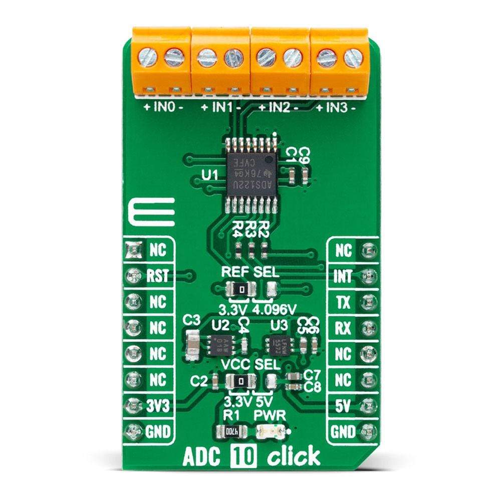
Besides its internal 2.048V reference, the ADS122U04 can use additional reference voltage values for applications that require a different reference voltage or a ratiometric measurement approach. The reference voltage level can be selected by positioning the SMD jumper labelled as REF SEL to an appropriate position choosing between 3.3V provided by the MCP1501 or 4.096V provided by LT6656. Those voltages may be used as the reference input that results in accuracy and stability.
The ADC 10 Click Board™ is designed to operate with both 3.3V and 5V logic voltage levels selected via the VCC SEL jumper. It allows for both 3.3V and 5V capable MCUs to use the UART communication lines properly. However, the Click board™ comes equipped with a library that contains functions and an example code that can be used, as a reference, for further development.
SPECIFICATIONS
| Type | ADC |
| Applications | Can be used for measuring small sensor signals, such as resistance temperature detectors (RTDs), thermocouples, thermistors, and resistive bridge sensors. |
| On-board modules | ADS122U04 - 24-bit precision ΔΣ analogue-to-digital converter with UART compatible interface from Texas Instruments MCP1501 - high-precision voltage reference from Microchip LT6656 - high-precision voltage reference from Analog Devices |
| Key Features | Low power consumption, programmable gain and data rates, two differential or four single-ended inputs, internal and external voltage references, internal temperature sensor, and more |
| Interface | UART |
| Compatibility | mikroBUS |
| Click board size | M (42.9 x 25.4 mm) |
| Input Voltage | 3.3V or 5V |
PINOUT DIAGRAM
This table shows how the pinout on the ADC 10 Click Board™ corresponds to the pinout on the mikroBUS™ socket (the latter shown in the two middle columns).
| Notes | Pin | Pin | Notes | ||||
|---|---|---|---|---|---|---|---|
| NC | 1 | AN | PWM | 16 | NC | ||
| Reset | RST | 2 | RST | INT | 15 | INT | Interrupt |
| NC | 3 | CS | RX | 14 | TX | UART TX | |
| NC | 4 | SCK | TX | 13 | RX | UART RX | |
| NC | 5 | MISO | SCL | 12 | NC | ||
| NC | 6 | MOSI | SDA | 11 | NC | ||
| Power Supply | 3.3V | 7 | 3.3V | 5V | 10 | 5V | Power Supply |
| Ground | GND | 8 | GND | GND | 9 | GND | Ground |
ONBOARD SETTINGS AND INDICATORS
| Label | Name | Default | Description |
|---|---|---|---|
| LD1 | PWR | - | Power LED Indicator |
| JP3 | VCC SEL | Left | Logic Level Voltage Selection 3.3V/5V: Left position 3.3V, Right position 5V |
| JP1 | REF SEL | Left | Reference Level Voltage Selection 3.3V/4.096V: Left position 3V3, Right position 4.096V |
ADC 10 CLICK ELECTRICAL SPECIFICATIONS
| Description | Min | Typ | Max | Unit |
|---|---|---|---|---|
| Supply Voltage | 3.3 | - | 5 | V |
| Analog Input Supply Voltage | 3.3 | - | 5 | V |
| Resolution | 24 | - | - | bits |
| Gain | 1 | - | 128 | |
| Data Rates | - | - | 2000 | SPS |
| Operating Temperature Range | -40 | +25 | +125 | °C |
| General Information | |
|---|---|
Part Number (SKU) |
MIKROE-4488
|
Manufacturer |
|
| Physical and Mechanical | |
Weight |
0.02 kg
|
| Other | |
EAN |
8606027381713
|
Frequently Asked Questions
Have a Question?
Be the first to ask a question about this.