

Mikroelektronika d.o.o.
Opto 5 Click Board™
Opto 5 Click Board™
SKU: MIKROE-4476
Couldn't load pickup availability


Overview
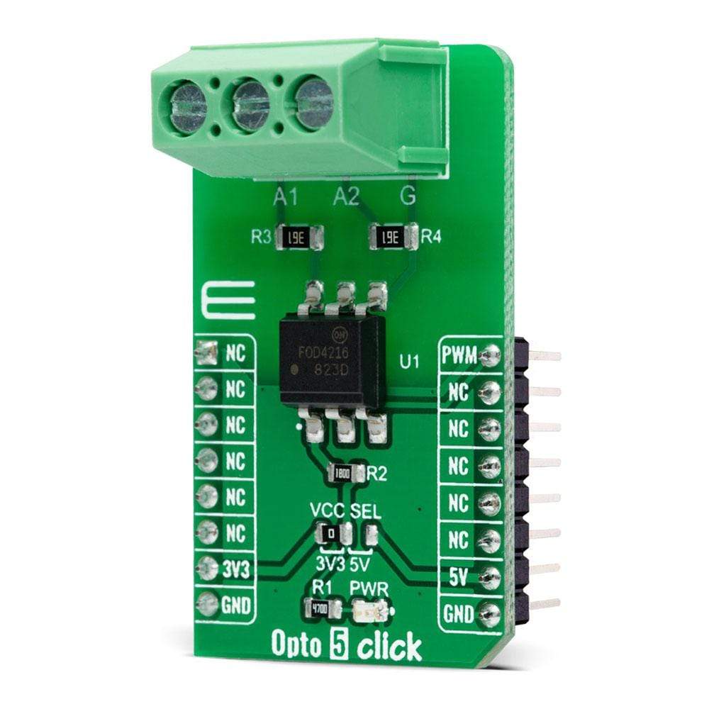
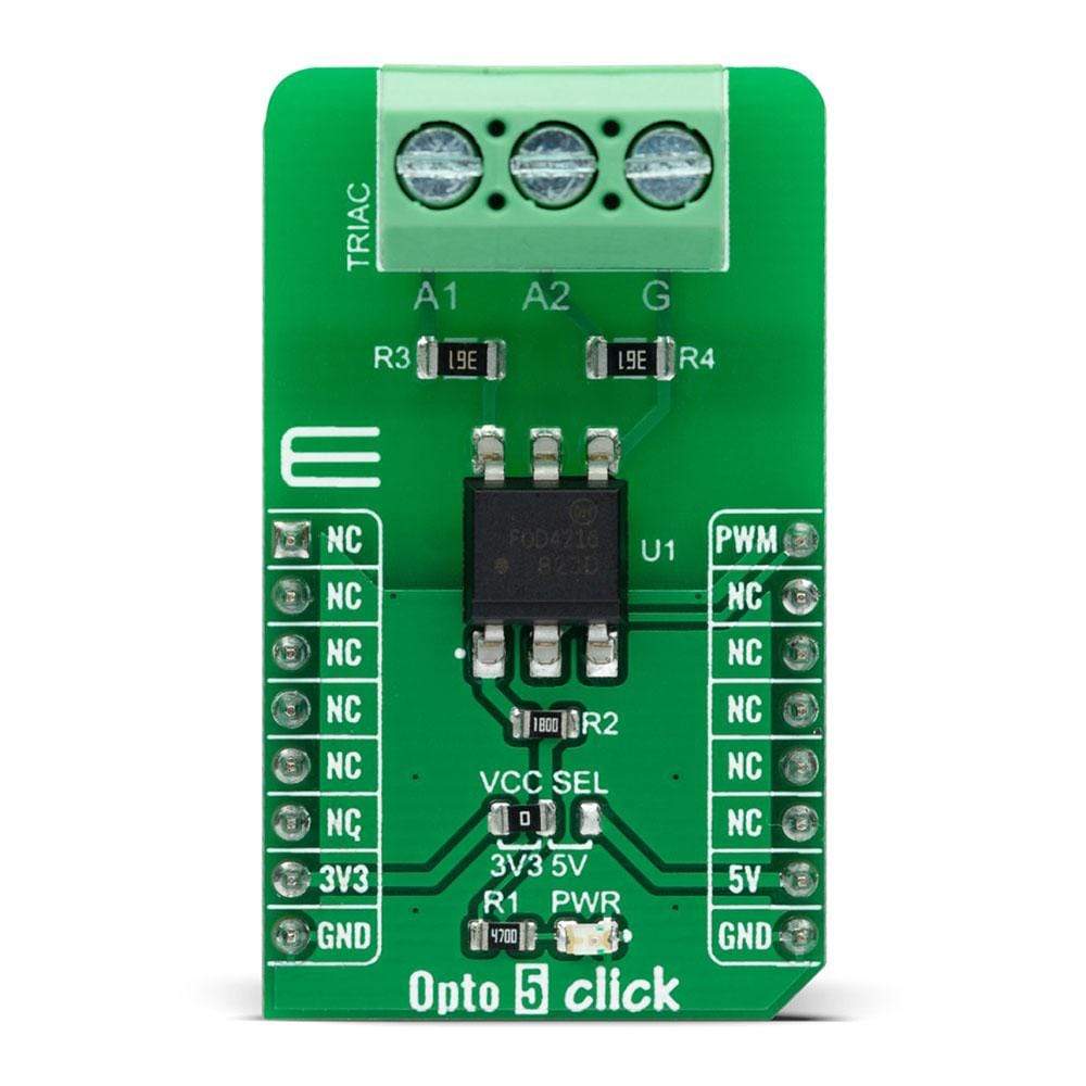
The Opto 5 Click Board™ is a compact add-on board that provides uncomplicated safety isolation from the high voltage. This board features the FOD4216, a random phase snubber-less Triac driver from ON Semiconductor. The FOD4216 consists of an infrared emitting diode coupled to a hybrid random phase triac formed with two inverse parallel SCRs, which creates the triac function capable of driving discrete triacs. It utilizes a high efficiency infrared emitting diode that offers an improved trigger sensitivity. This Click Board™ is suitable for applications like high voltage AC switching where there is a need to protect and electrically isolate two circuits in a switching application.
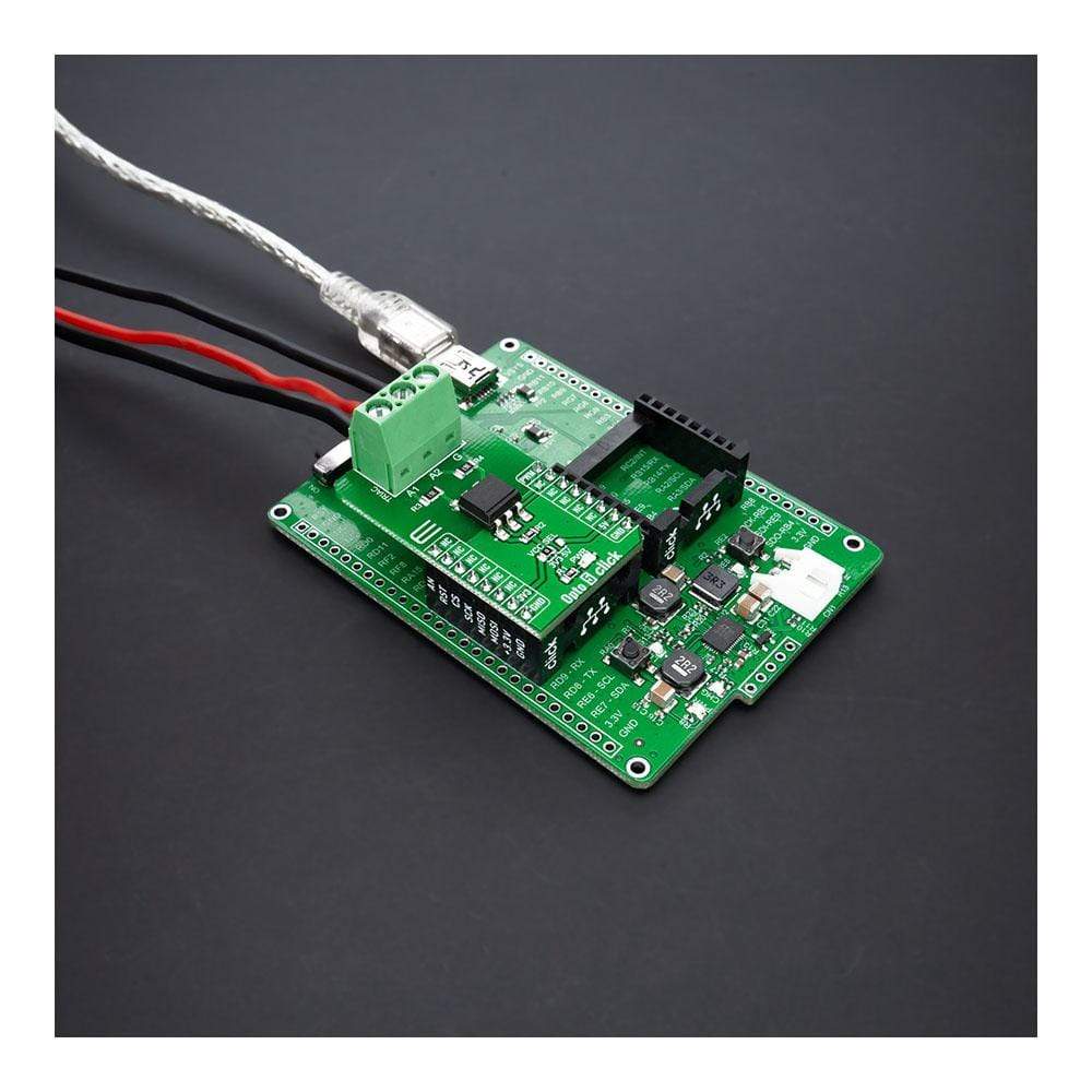
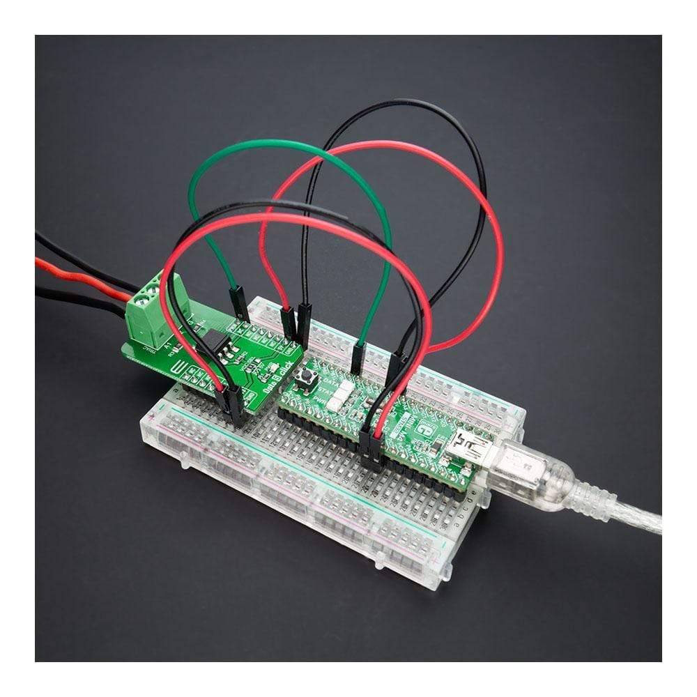
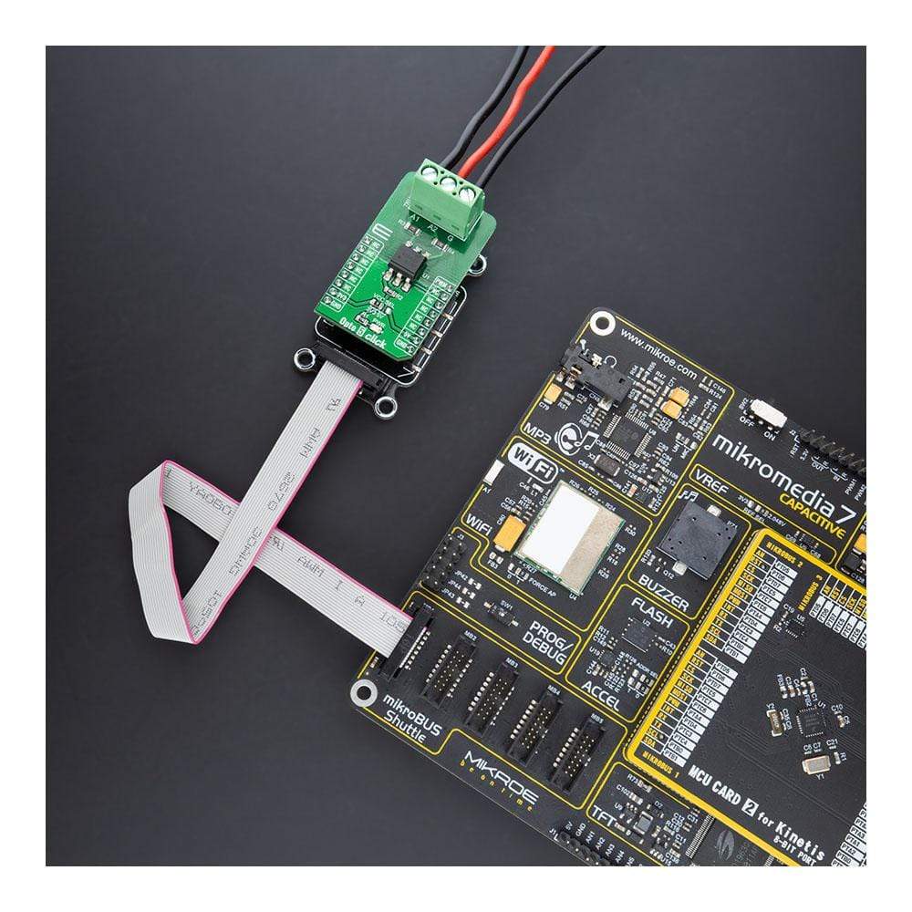
The Opto 5 Click Board™ is supported by a mikroSDK compliant library, which includes functions that simplify software development. This Click Board™ comes as a fully tested product, ready to be used on a system equipped with the mikroBUS™ socket.
Downloads
How Does The Opto 5 Click Board™ Work?
The Opto 5 Click Board™ is based on the FOD4216, a random phase snubberless Triac driver that provides uncomplicated high voltage safety isolation from ON Semiconductor. It utilizes a high efficiency infrared emitting diode that offers an improved trigger sensitivity coupled to a hybrid random phase triac formed with two inverse parallel SCRs, which creates the triac function capable of driving discrete triacs. It provides electrical isolation between a low voltage input and a high voltage output while switching the high voltage output.

The Triac stands for triode for alternating current and is a device that can conduct current in either direction when it is triggered or turned on by detecting a light beam on its trigger junction (Gate). The Triac changes from the off-state to the conducting state when a current, or current pulses are applied to the control electrode (Gate). Turning on the device can be achieved while synchronizing with the input voltage, whereas turn-off occurs when the current passes through zero following the control signal removal.
The Opto 5 Click Board™ operates only with the PWM signal from the mikroBUS™ socket that drives the cathode of the FOD4216. In applications when hot-line switching is required, the "hot" side of the line is switched, and the load is connected to the cold or neutral side. In the case of a Standard Triac usage, the user should add a 39Ω resistor and 0.01uF capacitor parallel to triac terminals A1 and A2 used for snubbing of the triac. While in the case of highly inductive loads where the power factor is lower than 0.5), the value of a resistor should be 360Ω. In the case of use Snubberless Triac usage, there is no need for these components.
NOTE: This optoisolator should not be used to drive a load directly. It is intended to be a discrete triac driver device only.
The Opto 5 Click Board™ is designed to operate with both 3.3V and 5V logic voltage levels selected via the VCC SEL jumper, which allows the use of both 3.3V and 5V capable MCUs. This Click board™ comes equipped with a library that contains functions and an example code that can be used, as a reference, for further development.
SPECIFICATIONS
| Type | Optocoupler |
| Applications | Can be used for applications like high voltage AC switching where there is a need to protect and electrically isolate two circuits in a switching application. |
| On-board modules | FOD4216, a random phase snubberless Triac driver that provides uncomplicated high voltage safety isolation from ON Semiconductor. |
| Key Features | High blocking voltage, high trigger sensitivity, high static dv/dt, high efficiency infrared emitting diode, and more. |
| Interface | PWM |
| Compatibility | mikroBUS |
| Click board size | M (42.9 x 25.4 mm) |
| Input Voltage | 3.3V or 5V |
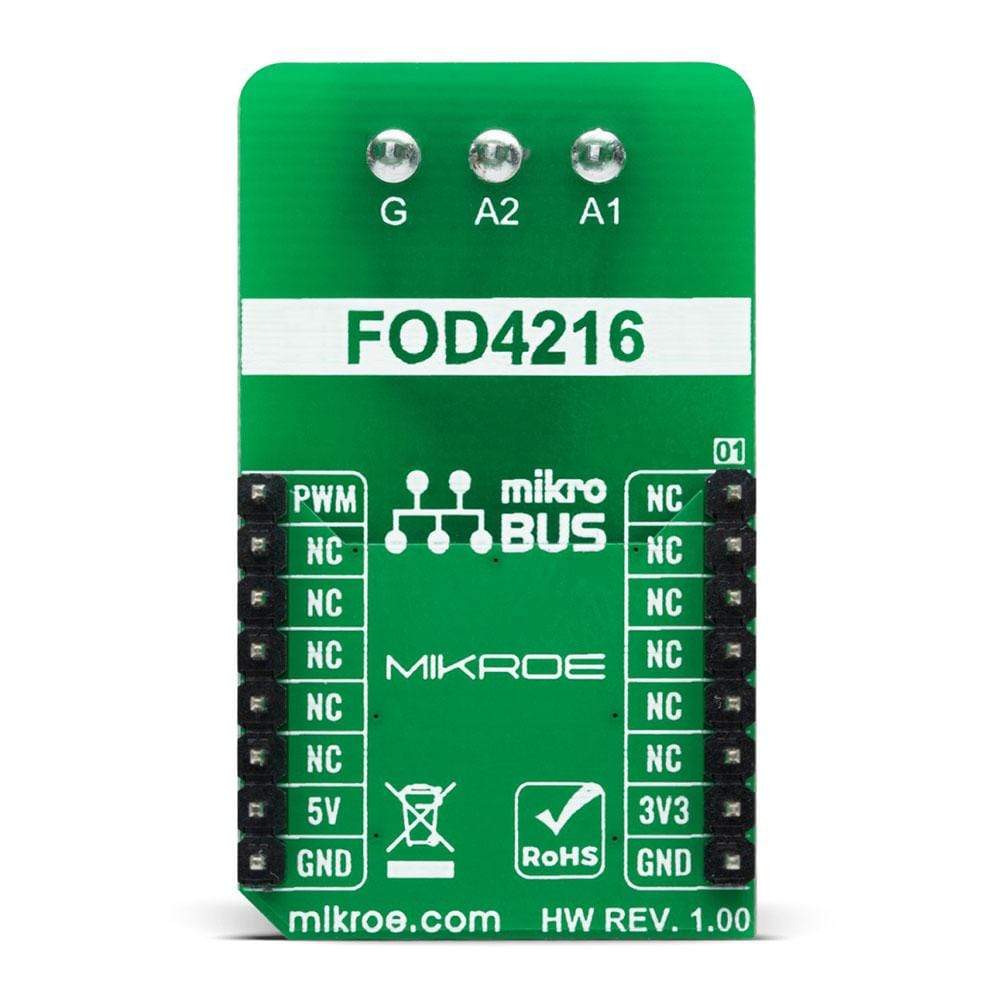
PINOUT DIAGRAM
This table shows how the pinout on the Opto 5 Click Board™ corresponds to the pinout on the mikroBUS™ socket (the latter shown in the two middle columns).
| Notes | Pin | Pin | Notes | ||||
|---|---|---|---|---|---|---|---|
| NC | 1 | AN | PWM | 16 | PWM | PWM Signal | |
| NC | 2 | RST | INT | 15 | NC | ||
| NC | 3 | CS | RX | 14 | NC | ||
| NC | 4 | SCK | TX | 13 | NC | ||
| NC | 5 | MISO | SCL | 12 | NC | ||
| NC | 6 | MOSI | SDA | 11 | NC | ||
| Power Supply | 3.3V | 7 | 3.3V | 5V | 10 | 5V | Power Supply |
| Ground | GND | 8 | GND | GND | 9 | GND | Ground |
ONBOARD SETTINGS AND INDICATORS
| Label | Name | Default | Description |
|---|---|---|---|
| LD1 | PWR | - | Power LED Indicator |
| JP1 | VCC SEL | Left | Logic Level Voltage Selection 3V3/5V: Left position 3V3, Right position 5V |
OPTO 5 CLICK ELECTRICAL SPECIFICATIONS
| Description | Min | Typ | Max | Unit |
|---|---|---|---|---|
| Supply Voltage | 3.3 | - | 5 | V |
| Off−State Output Terminal Voltage | - | - | 600 | V |
| Isolation Voltage | 5000 | - | - | Vrms |
| Maximum LED Trigger Current | - | - | 1.3 | mA |
| Operating Temperature Range | -55 | +25 | +100 | °C |
| General Information | |
|---|---|
Part Number (SKU) |
MIKROE-4476
|
Manufacturer |
|
| Physical and Mechanical | |
Weight |
0.021 kg
|
| Other | |
EAN |
8606027381690
|
Frequently Asked Questions
Have a Question?
Be the first to ask a question about this.