


Mikroelektronika d.o.o.
SKU: MIKROE-4413Clock Gen 5 Click Board
Clock Gen 5 Click Board
Couldn't load pickup availability
Key Features
- Low power consumption, more reliable and vastly more versatile clocking solution, precision frequency from 1kHz to 68MHz, proprietary feedback loop, and more.
- Based on the LTC6903 - a low-power self-contained digital frequency source providing a precision frequency from 1kHz to 68MHz set through a 3-wire digital interface from Analog Devices.
- Can be used for applications such as MCU clock source, clock source for a switched capacitor filter, or general replacement for a DAC/VCO combination
- mikroBUS: SPI Interface
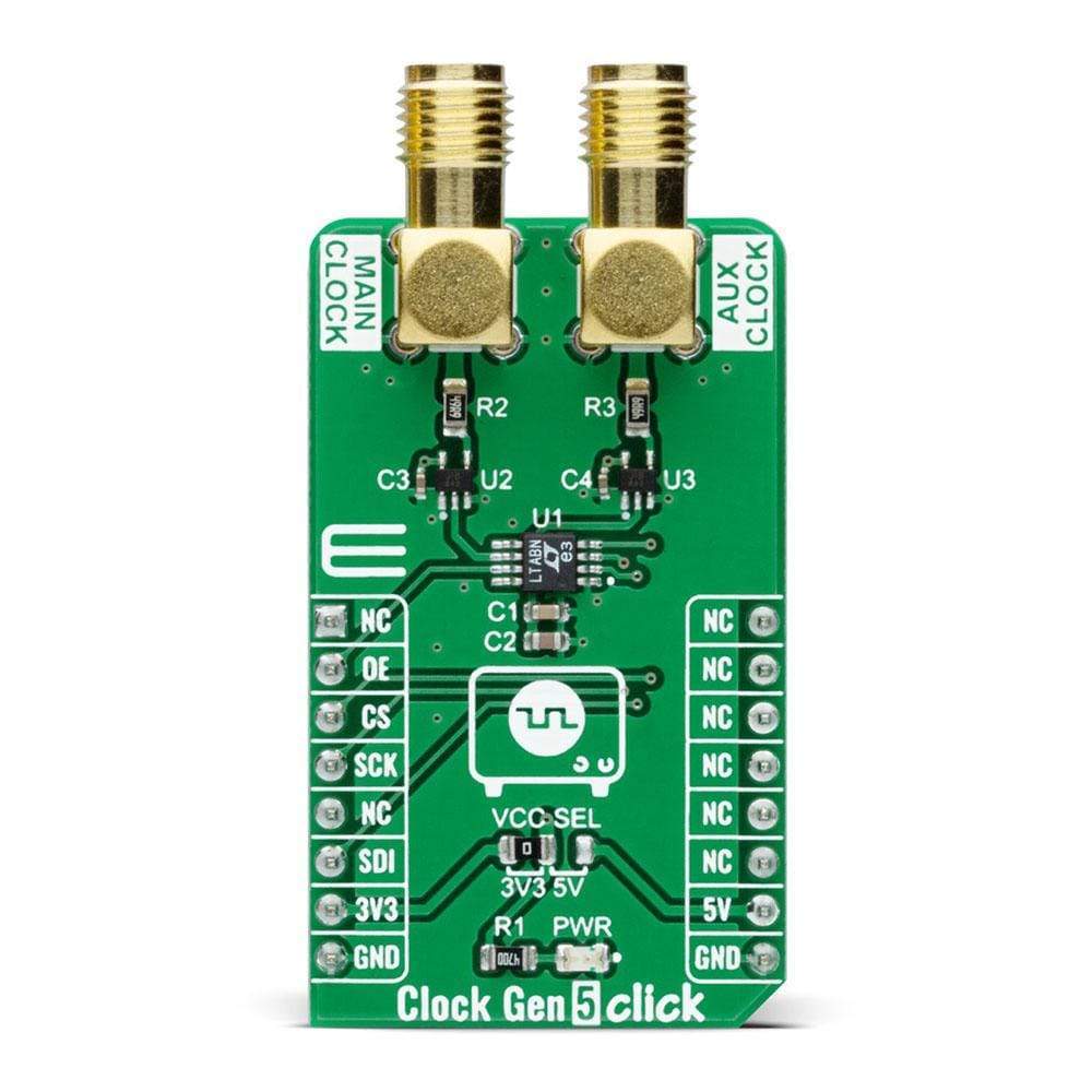
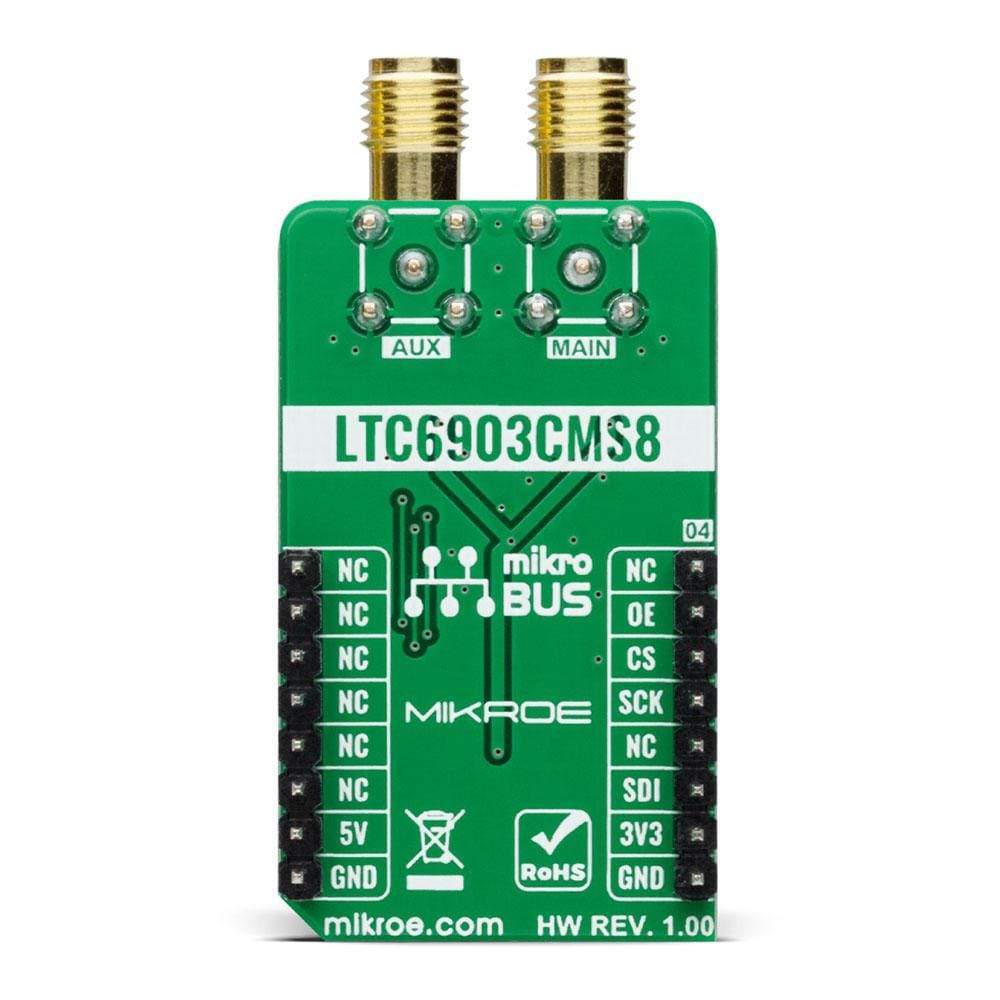
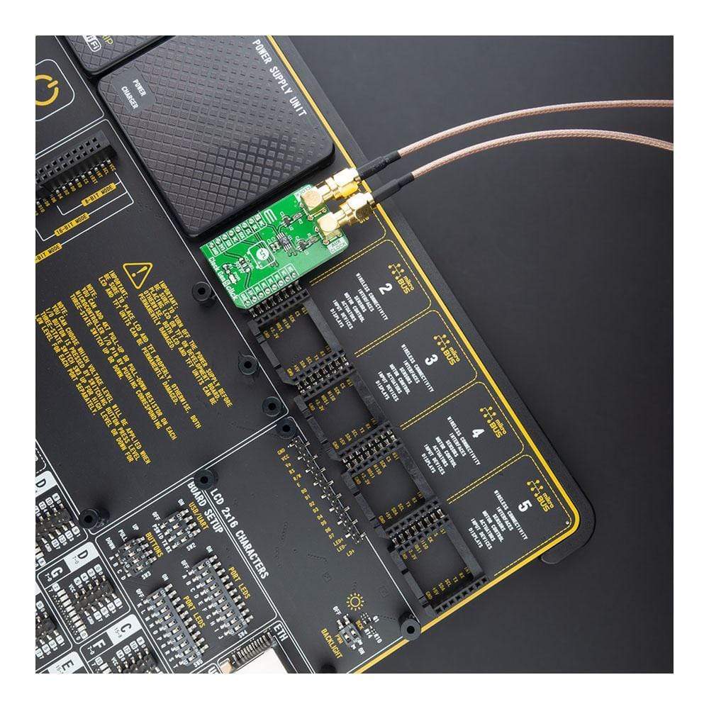
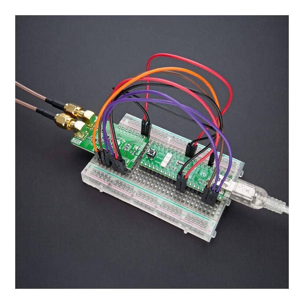
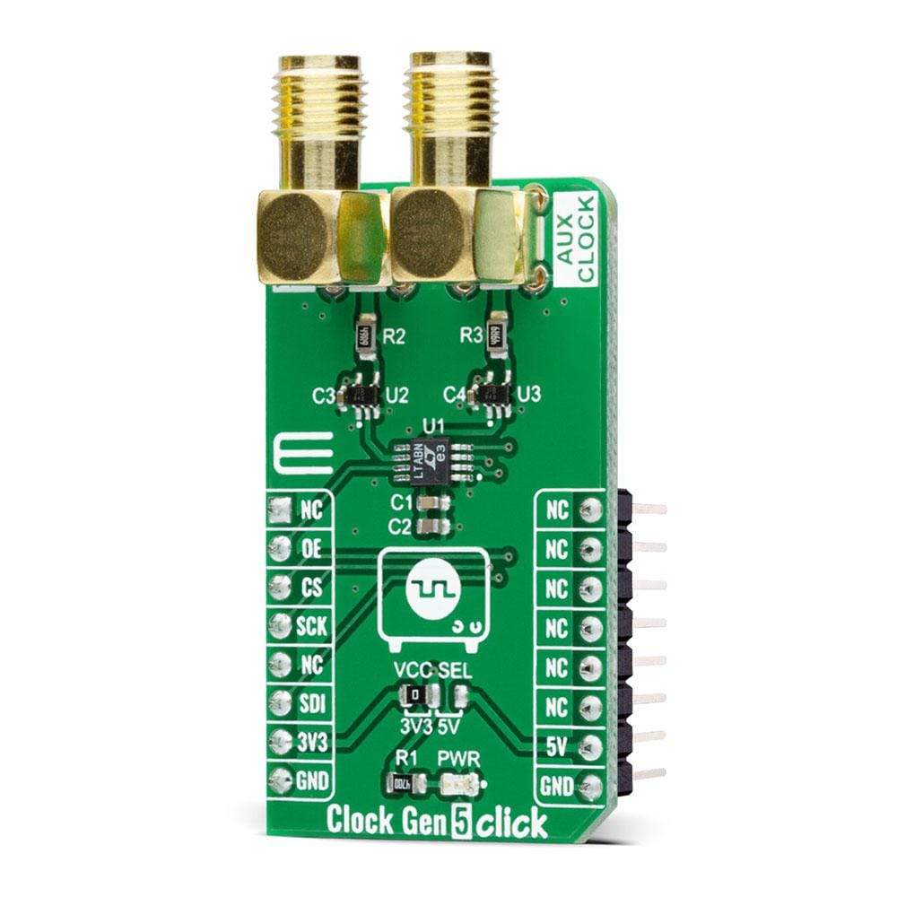
The Clock Gen 5 Click Board™ is a compact add-on board that contains a digital programmable oscillator solution. This board features the LTC6903, a low-power self-contained digital frequency source providing a precision frequency from 1kHz to 68MHz set through a 3-wire SPI digital interface from Analog Devices. The LTC6903 features a proprietary feedback loop that linearizes the relationship between digital control setting and frequency and provides a smaller, more reliable, and vastly more versatile clocking solution. The frequency between 1kHz and 68MHz is set by a 16-bit control word, typically accurate within 1.1% with a resolution of 0.1% or better. This Click Board™ is suitable for applications such as MCU clock source, clock source for a switched capacitor filter, or general replacement for a DAC/VCO combination.
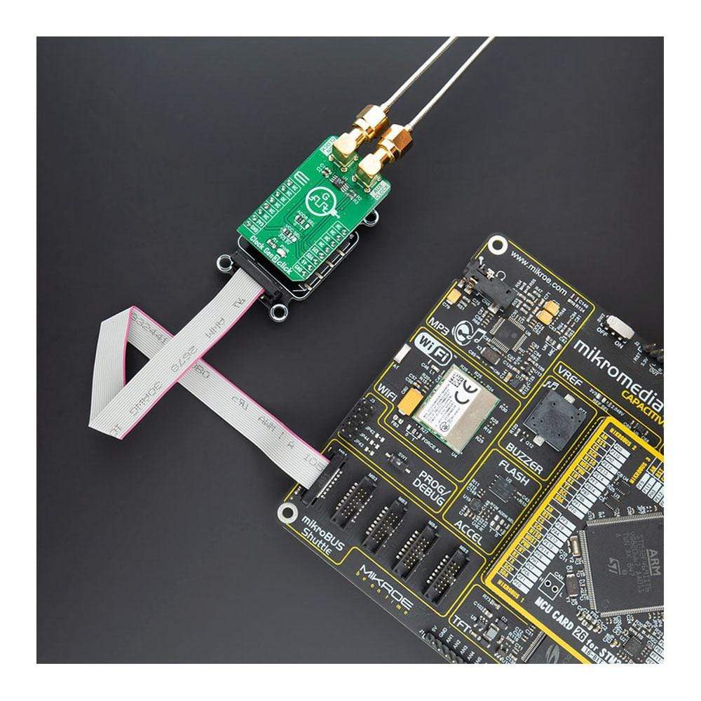
The Clock Gen 5 Click Board™ is supported by a mikroSDK compliant library, which includes functions that simplify software development. This Click Board™ comes as a fully tested product, ready to be used on a system equipped with the mikroBUS™ socket.


How Does The Clock Gen 5 Click Board™ work?
The Clock Gen 5 Click Board™ is based on the LTC6903, a low-power self-contained digital frequency source providing a precision frequency from 1kHz to 68MHz set through a 3-wire digital interface from Analog Devices. The LTC6903 contains an internal feedback loop that controls a high-frequency square wave (VCO) operating between 34MHz and 68MHz. It is also a resistor controlled oscillator that offers an integrated serial resistor DAC and a set of digital frequency dividers. The oscillator frequency is inversely proportional to the resistance of the DAC, where step size ranges between 0.05% and 0.1% of the frequency.

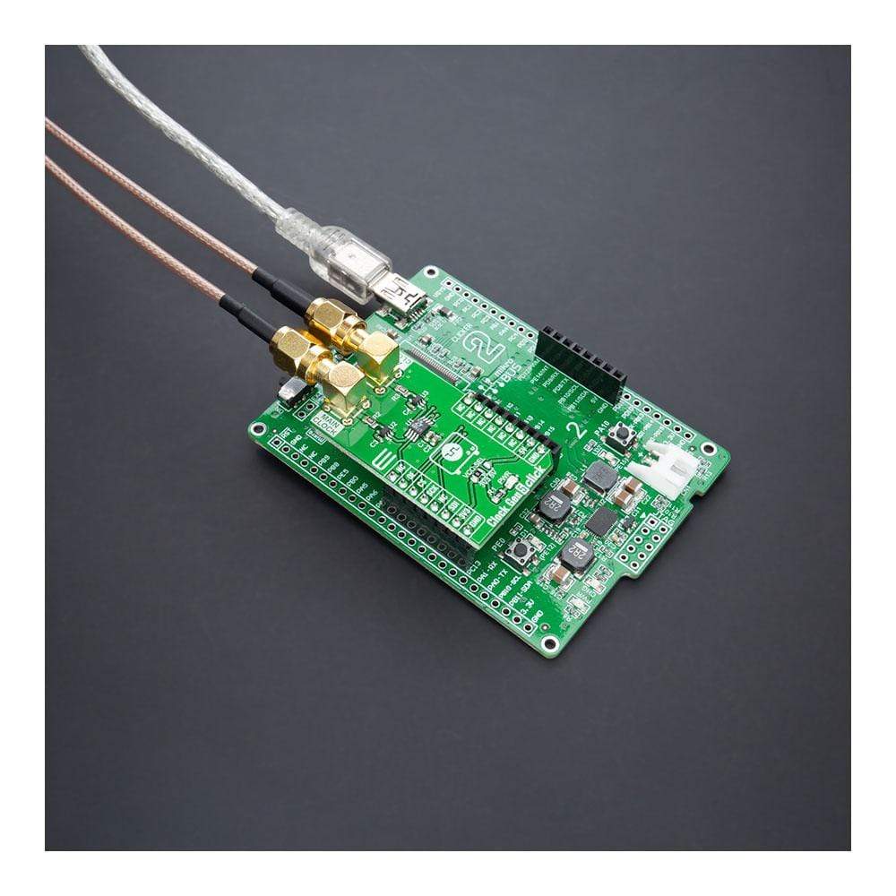
In the most frequency ranges, the output of the Clock Gen 5 Click Board™ is generated as a division of the higher internal clock frequency. This helps to minimize jitter and sub-harmonics at the output of the device. In the highest frequency ranges, the division ratio is reduced, which will result in greater cycle-to-cycle jitter as well as spurs at the internal sampling frequency. The output clock signals, available on the SMA connectors with an impedance of 50Ω labelled as MAIN and AUX CLOCK, before the output itself are primarily conducted through the TC7SZ125FU, a 3-state bus buffer allowing the LTC6903 to operate normally producing the required output.
The Clock Gen 5 Click Board™ communicates with MCU using the 3-Wire SPI serial interface and operates at a clock frequency up to 20 MHz. The output signals are controlled by the output control bits MODE1 and MODE0, where the outputs can be disabled through these bits. When both output signals are disabled through the mode control bits, the internal oscillator is also disabled. The OE pin, routed on the RST pin of the mikroBUS™ socket, can also be used to asynchronously disable either output without shutting down the oscillator entirely.
The Clock Gen 5 Click Board™ is designed to operate with both 3.3V and 5V logic voltage levels selected via the VCC SEL jumper. It allows for both 3.3V and 5V capable MCUs to use the SPI communication lines properly. However, the Click board™ comes equipped with a library that contains functions and an example code that can be used, as a reference, for further development.
SPECIFICATIONS
| Type | Clock generator |
| Applications | Can be used for applications such as MCU clock source, clock source for a switched capacitor filter, or general replacement for a DAC/VCO combination |
| On-board modules | LTC6903 - a low-power self-contained digital frequency source providing a precision frequency from 1kHz to 68MHz set through a 3-wire digital interface from Analog Devices. |
| Key Features | Low power consumption, more reliable and vastly more versatile clocking solution, precision frequency from 1kHz to 68MHz, proprietary feedback loop, and more. |
| Interface | SPI |
| Compatibility | mikroBUS |
| Click board size | M (42.9 x 25.4 mm) |
| Input Voltage | 3.3V or 5V |
PINOUT DIAGRAM
This table shows how the pinout on the Clock Gen 5 Click Board™ corresponds to the pinout on the mikroBUS™ socket (the latter shown in the two middle columns).
| Notes | Pin | Pin | Notes | ||||
|---|---|---|---|---|---|---|---|
| NC | 1 | AN | PWM | 16 | NC | ||
| Asynchronous Enable | OE | 2 | RST | INT | 15 | NC | |
| SPI Chip Select | CS | 3 | CS | RX | 14 | NC | |
| SPI Clock | SCK | 4 | SCK | TX | 13 | NC | |
| NC | 5 | MISO | SCL | 12 | NC | ||
| SPI Data IN | SDI | 6 | MOSI | SDA | 11 | NC | |
| Power Supply | 3.3V | 7 | 3.3V | 5V | 10 | 5V | Power Supply |
| Ground | GND | 8 | GND | GND | 9 | GND | Ground |
ONBOARD SETTINGS AND INDICATORS
| Label | Name | Default | Description |
|---|---|---|---|
| LD1 | PWR | - | Power LED Indicator |
| JP1 | VCC SEL | Left | Logic Level Voltage Selection 3V3/5V: Left position 3V3, Right position 5V |
CLOCK GEN 5 CLICK ELECTRICAL SPECIFICATIONS
| Description | Min | Typ | Max | Unit |
|---|---|---|---|---|
| Supply Voltage | 3.3 | - | 5 | V |
| Frequency Range | 0.001 | - | 68 | MHz |
| Operating Temperature Range | -40 | +25 | +85 | °C |
Software Support
We provide a library for the Clock Gen 5 Click Board™ on our LibStock page, as well as a demo application (example), developed using MikroElektronika compilers. The demo can run on all the main MikroElektronika development boards.
The package can be downloaded/installed directly from NECTO Studio Package Manager(recommended way), downloaded from our LibStock™ or found on the mikroE Github account.
Library Description
The library covers all the necessary functions to control the Clock Gen 5 Click Board™. The library performs a standard SPI interface communication.
Key Functions
void clockgen5_out_enable ( uint8_t en_out )- Enable output function.void clockgen5_set_config ( uint8_t cfg )- Set configuration function.void clockgen5_set_freq ( float freq )- Set frequency function.
Example Description
The application is composed of three sections :
- System Initialization - Initializes SPI, set RST and CS pin as outputs, begins to write log.
- Application Initialization - Initialization driver enables - SPI, set output configuration CLK + 180°, also write log.
- Application Task - (code snippet) This is an example that demonstrates the use of the Clock Gen 5 Click board™. In this example, we adjust different frequencies every 3 sec. Results are being sent to the USART Terminal where you can track their changes.
void application_task ( )
{
    clockgen5_set_freq( 12000.0 );
    mikrobus_logWrite( "-----------------------", _LOG_LINE );
    mikrobus_logWrite( "        12.0 MHz       ", _LOG_LINE );
    Delay_ms( 3000 );

    clockgen5_set_freq( 8000.0 );
    mikrobus_logWrite( "-----------------------", _LOG_LINE );
    mikrobus_logWrite( "         8.0 MHz       ", _LOG_LINE );
    Delay_ms( 3000 );

    clockgen5_set_freq( 5500.0 );
    mikrobus_logWrite( "-----------------------", _LOG_LINE );
    mikrobus_logWrite( "         5.5 MHz       ", _LOG_LINE );
    Delay_ms( 3000 );

    clockgen5_set_freq( 2700.0 );
    mikrobus_logWrite( "-----------------------", _LOG_LINE );
    mikrobus_logWrite( "         2.7 MHz       ", _LOG_LINE );
    Delay_ms( 3000 );

    clockgen5_set_freq( 800.0 );
    mikrobus_logWrite( "-----------------------", _LOG_LINE );
    mikrobus_logWrite( "         0.8 MHz       ", _LOG_LINE );
    Delay_ms( 3000 );

    clockgen5_set_freq( 200.0 );
    mikrobus_logWrite( "-----------------------", _LOG_LINE );
    mikrobus_logWrite( "         0.2 MHz       ", _LOG_LINE );
    Delay_ms( 3000 );
}
The full application code, and ready to use projects can be found on our LibStock page.
Other mikroE Libraries used in the example:
- SPI
- UART
Additional Notes and Information
Depending on the development board you are using, you may need a USB UART click, USB UART 2 click or RS232 click to connect to your PC, for development systems with no UART to USB interface available on the board. The terminal available in all MikroElektronika compilers, or any other terminal application of your choice, can be used to read the message.
MIKROSDK
The Clock Gen 5 Click Board™ is supported with mikroSDK - MikroElektronika Software Development Kit. To ensure proper operation of mikroSDK compliant Click board™ demo applications, mikroSDK should be downloaded from the LibStock and installed for the compiler you are using.
Clock Gen 5 Click Board
Frequently Asked Questions
Have a Question?
Be the first to ask a question about this.