


Mikroelektronika d.o.o.
DC Motor 15 Click Board™
DC Motor 15 Click Board™
SKU: MIKROE-4334
Couldn't load pickup availability


Overview
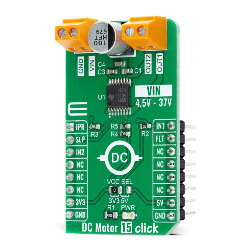
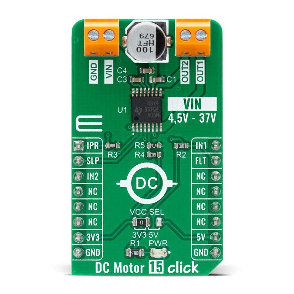
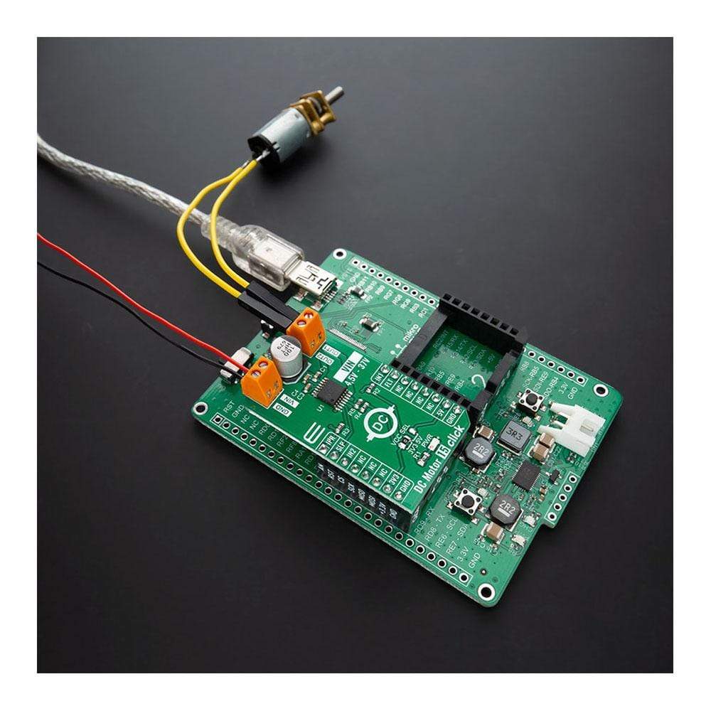
The DC Motor 15 Click Board™ is a compact add-on board that contains a motor driver with current sense and regulation. This board features the DRV8874, an integrated motor driver with N-channel H-bridge, charge pump, current sensing, and adjustment from Texas Instruments. The current sensing and regulation feature eliminates the need for a large power shunt resistor, saving board area, and reducing system cost. The current-sense output allows an MCU to detect motor stalls or changes in load conditions. The DRV8874 can also regulate the motor current during Start-Up and high-load events without interaction from MCU. This Click Board™ is suitable for a brushed DC and servo motor and actuator drive, home appliances, handheld power tools, and many more.
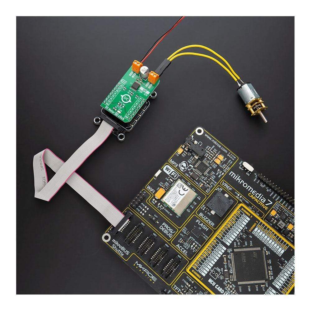
The DC Motor 15 Click is supported by a mikroSDK compliant library, which includes functions that simplify software development. This Click Board™ comes as a fully tested product, ready to be used on a system equipped with the mikroBUS™ socket.
Downloads
How Does The DC Motor 15 Click Board™ Work?
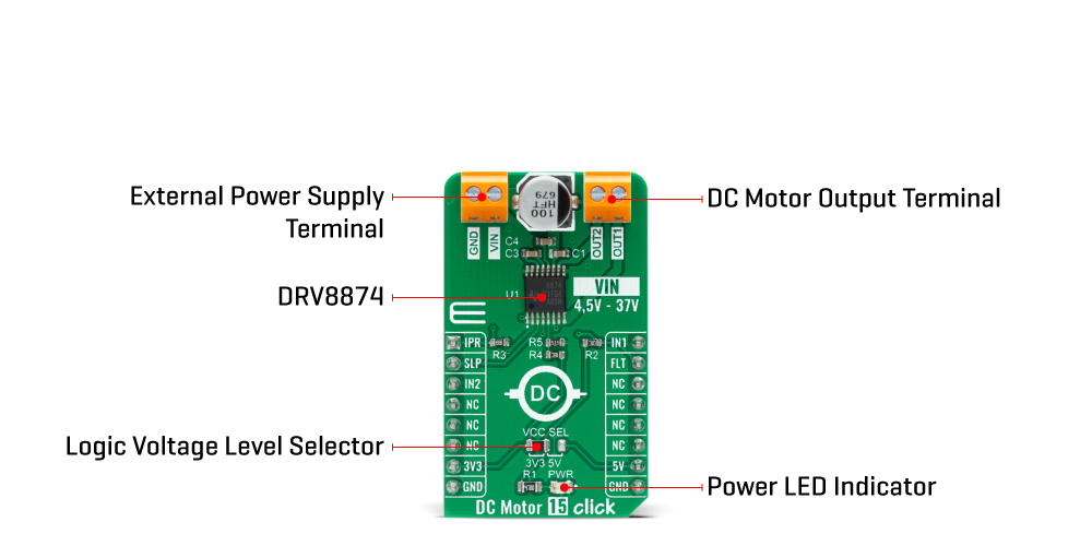
The DC Motor 15 Click Board™ is based on the DRV8874, an integrated motor driver with N-channel H-bridge, charge pump, current sensing and proportional output, current regulation, and protection circuitry from Texas Instruments. The DRV8874 operates from the external power supply from 4.5V to 37V providing a wide range of output load currents for various types of motors and loads. The charge pump feature improves efficiency by supporting N-channel MOSFET half-bridges and 100% duty cycle driving. This Click board™ also integrates current sensing, regulation, and feedback. These features allow for the DRV8874 to sense the output current without an external sense resistor or sense circuitry reducing system cost and complexity. This also allows for the device to limit the output current in the case of the motor stall or high torque events and give detailed feedback to the MCU about the load current through a current proportional output on the AN pin of the mikroBUS™ labeled as IPR.
The DRV8874 integrates an H-bridge output power stage that can be operated in different control modes set by the PMODE pin setting. The PMODE pin on this Click board™ is set to a logic low level that means that the device is latched into PH/EN mode. PH/EN mode allows for the H-bridge to be controlled with a speed and direction type of interface through two GPIO pins labeled as IN2 and IN1, routed to the PWM and CS pins of the mikroBUS™ socket. It also has a Sleep Mode that achieves ultra-low quiescent current draw by shutting down most of the internal circuitry. The SLP pin routed to the RST pin of the mikroBUS™ socket provides an ultra-low power mode to minimize current draw during system inactivity.
The DC Motor 15 Click Board™ communicates with MCU using several GPIO pins as mentioned before in the product description. In addition to the pins used to adjust the speed and rotation direction of the motor, this Click board™ also has an interrupt labeled as FLT routed to the INT pin of the mikroBUS™ socket used to protect the device and the output load. The DRV8874 enters a Fault Mode when a fault is encountered, and leave the Fault Mode, and re-enter the Active Mode when the recovery condition is met.
The DC Motor 15 Click Board™ is designed to be operated with both 3.3V and 5V logic voltage levels that can be selected via VCC SEL jumper. This allows for both 3.3V and 5V capable MCUs to use the GPIO lines properly. However, the Click board™ comes equipped with a library that contains easy to use functions and an example code that can be used as a reference for further development.
SPECIFICATIONS
| Type | Brushed |
| Applications | Can be used for a brushed DC and servo motor and actuator drive, home appliances, handheld power tools, and many more. |
| On-board modules | The DC Motor 15 Click Board™ is based on the DRV8874, an integrated motor driver with N-channel H-bridge, charge pump, current sensing and proportional output, current regulation, and protection circuitry from Texas Instruments. |
| Key Features | High output current capability, integrated current sensing and regulation, proportional current output, selectable current regulation and control modes, low power consumption, and more. |
| Interface | GPIO |
| Compatibility | mikroBUS |
| Click board size | M (42.9 x 25.4 mm) |
| Input Voltage | 3.3V or 5V |
PINOUT DIAGRAM
This table shows how the pinout of thenC Motor 15 Click Board™ corresponds to the pinout on the mikroBUS™ socket (the latter shown in the two middle columns).
| Notes | Pin | Pin | Notes | ||||
|---|---|---|---|---|---|---|---|
| Analog Current Output | IPR | 1 | AN | PWM | 16 | IN1 | Motor control input 1 |
| Sleep Mode | SLP | 2 | RST | INT | 15 | FLT | Fault Indicator |
| Motor Control Input 2 | IN2 | 3 | CS | RX | 14 | NC | |
| NC | 4 | SCK | TX | 13 | NC | ||
| NC | 5 | MISO | SCL | 12 | NC | ||
| NC | 6 | MOSI | SDA | 11 | NC | ||
| Power Supply | 3.3V | 7 | 3.3V | 5V | 10 | 5V | Power Supply |
| Ground | GND | 8 | GND | GND | 9 | GND | Ground |
ONBOARD SETTINGS AND INDICATORS
| Label | Name | Default | Description |
|---|---|---|---|
| LD1 | PWR | - | Power LED Indicator |
| JP1 | VCC SEL | Left | Power Supply Voltage Selection 3V3/5V: Left position 3V3, Right position 5V |
DC MOTOR 15 CLICK ELECTRICAL SPECIFICATIONS
| Description | Min | Typ | Max | Unit |
|---|---|---|---|---|
| Supply Voltage | 4.5 | - | 3.7 | V |
| Maximum Output Current | 0 | - | 6 | A |
| Current sense output current | - | - | 3 | mA |
| Operating Temperature Range | -40 | - | +125 | °C |
| General Information | |
|---|---|
Part Number (SKU) |
MIKROE-4334
|
Manufacturer |
|
| Physical and Mechanical | |
Weight |
0.02 kg
|
| Other | |
EAN |
8606027380907
|
Frequently Asked Questions
Have a Question?
Be the first to ask a question about this.