


Mikroelektronika d.o.o.
SKU: MIKROE-43306DOF IMU 15 Click Board
6DOF IMU 15 Click Board
Couldn't load pickup availability
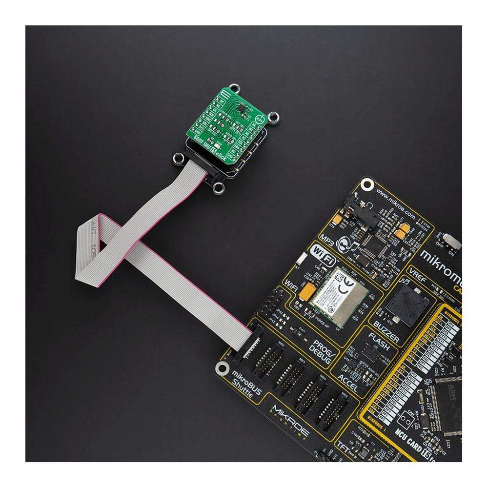
The 6DOF IMU 15 Click Board™ is a compact add-on board that contains a 6-axis MEMS motion tracking device combining a 3-axis gyroscope and a 3-axis accelerometer. This board features the ASM330LHH, an automotive 6-axis MEMS motion tracking device, from STMicroelectronics. It has a configurable host interface that supports both I2C and SPI serial communication, features a 3 kB FIFO and a programmable interrupt with ultra-low-power event-detection support to minimize system power consumption. This Click Board™ is an excellent choice for applications like gesture recognition, activity classification, dead reckoning, pedometers, Telematics, eTolling, anti-theft systems, and more.
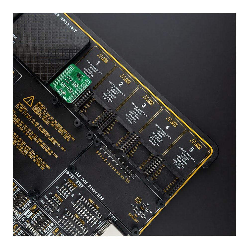
The 6DOF IMU 15 Click is supported by a mikroSDK compliant library, which includes functions that simplify software development. This Click Board™ comes as a fully tested product, ready to be used on a system equipped with the mikroBUS™ socket.
How Does The 6DOF IMU 15 Click Board™ Work?
The 6DOF IMU 15 Click Board™ is based on the ASM330LHH, a system-in-package featuring a high-performance 3-axis digital accelerometer and 3-axis digital gyroscope from STMicroelectronics. It features a 3 kB FIFO that can lower the traffic on the serial bus interface, and reduce power consumption by allowing the system processor to burst read sensor data, and then go into a low-power mode. It also features embedded compensation for high stability over temperature (up to +105 °C). The ASM330LHH has a configurable full-scale acceleration range of up to ±16 g and a wide angular rate range, from ±125 dps up to ±4000 dps, that enables its usage in a broad range of applications.
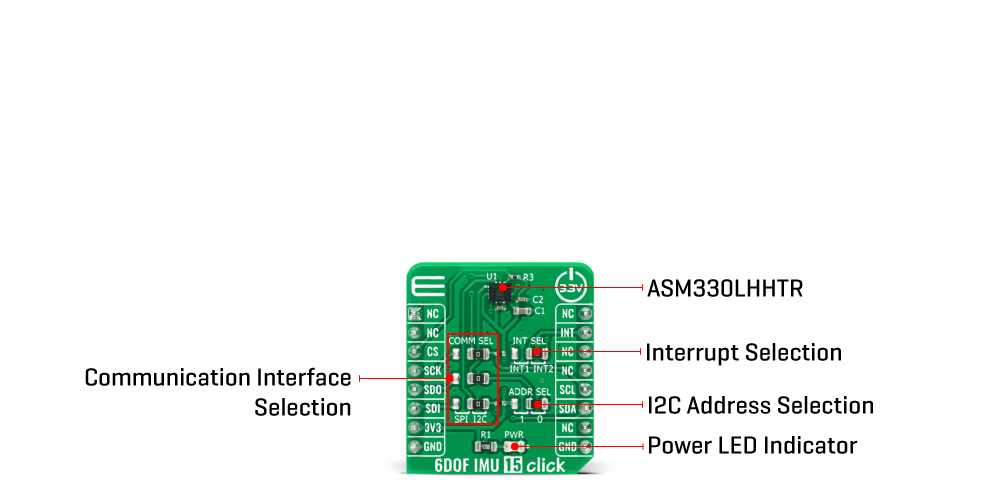
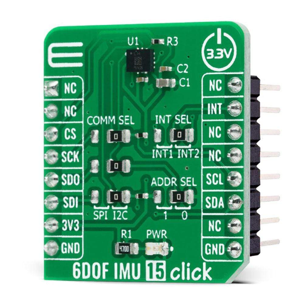
The ASM330LHH has a programmable interrupt system that can generate an interrupt signal for two available pins. One of these two interrupt pins can be selected using the INT SEL jumper (JP4), which is routed to the INT pin of the mikroBUS™ socket. The event-detection smart programmable interrupts enable efficient and reliable motion-activated functions, implementing hardware recognition of free-fall events, 6D orientation, activity or inactivity, and wakeup events.
The 6DOF IMU 15 Click Board™ provides the possibility of using both I2C and SPI interfaces with a maximum frequency of 400kHz for I2C and 10MHz for SPI communication. The selection can be done by positioning SMD jumpers labelled as COMM SEL to an appropriate position. Note that all the jumpers must be placed to the same side, or else the Click board™ may become unresponsive. While the I2C interface is selected, the ASM330LHH allows the choice of the least significant bit (LSB) of its I2C slave address. This can be done by using the SMD jumper labelled as ADDR SEL.
A FIFO buffer helps to further reduce the processing load, offering temporary storage for the output data. The ASM330LHH contains a FIFO of size 3 Kbytes that is accessible via the serial interface. The FIFO configuration register determines which data is written into the FIFO. Possible choices include gyro data, accelerometer data, Timestamp, and temperature readings.
The 6DOF IMU 15 Click Board™ is designed to be operated only with a 3.3V logic level. A proper logic voltage level conversion should be performed before the Click board™ is used with MCUs with different logic levels.
SPECIFICATIONS
| Type | Acceleration,Gyroscope,Motion |
| Applications | Gesture recognition, activity classification, dead reckoning, pedometers, Telematics, eTolling, anti-theft systems, and more. |
| On-board modules | The 6DOF IMU 15 Click Board™ is based on the ASM330LHH, a system-in-package featuring a high-performance 3-axis digital accelerometer and 3-axis digital gyroscope from STMicroelectronics |
| Key Features | Both I2C and SPI serial communication features a 3 kB FIFO and a programmable interrupt with ultra-low-power event-detection support to minimize system power consumption, and more. |
| Interface | I2C,SPI |
| Compatibility | mikroBUS |
| Click board size | S (28.6 x 25.4 mm) |
| Input Voltage | 3.3V |
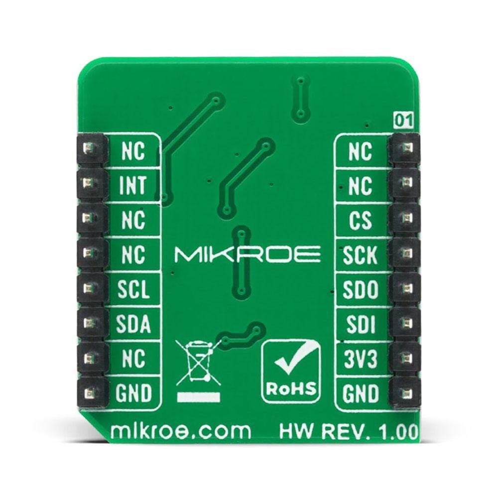
PINOUT DIAGRAM
This table shows how the pinout of the 6DOF IMU 15 Click Board™ corresponds to the pinout on the mikroBUS™ socket (the latter shown in the two middle columns).
| Notes | Pin | Pin | Notes | ||||
|---|---|---|---|---|---|---|---|
| NC | 1 | AN | PWM | 16 | NC | ||
| NC | 2 | RST | INT | 15 | INT | Interrupt | |
| SPI Chip Select | CS | 3 | CS | RX | 14 | NC | |
| SPI Clock | SCK | 4 | SCK | TX | 13 | NC | |
| SPI Data OUT | SDO | 5 | MISO | SCL | 12 | SCL | I2C Clock |
| SPI Data IN | SDI | 6 | MOSI | SDA | 11 | SDA | I2C Data |
| Power Supply | 3.3V | 7 | 3.3V | 5V | 10 | NC | |
| Ground | GND | 8 | GND | GND | 9 | GND | Ground |
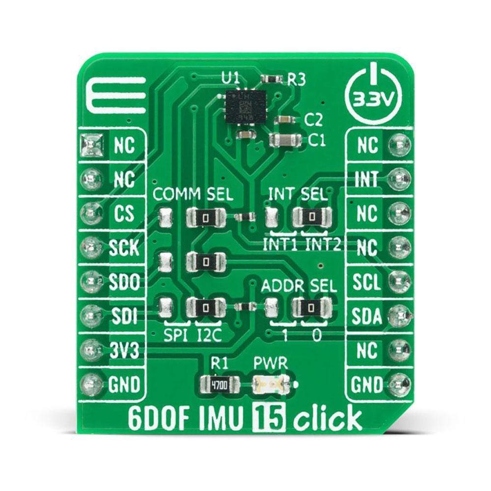
ONBOARD SETTINGS AND INDICATORS
| Label | Name | Default | Description |
|---|---|---|---|
| LD1 | PWR | - | Power LED Indicator |
| JP1-JP3 | COMM SEL | Right | Communication interface selection: left position SPI, right position I2C |
| JP4 | INT SEL | Right | Interrupt pin selection: left position INT 1, right position INT 2 |
| JP5 | ADDR SEL | Right | I2C Address Selection: Left position 0, Right position 1 |
6DOF IMU 15 CLICK ELECTRICAL SPECIFICATIONS
| Description | Min | Typ | Max | Unit |
|---|---|---|---|---|
| Supply Voltage | 2.0 | 3.3 | 3.6 | V |
| I2C Clock Frequency | - | - | 400 | kHz |
| SPI Clock Frequency | - | - | 10 | kHz |
| Linear acceleration measurement range | ±2 | - | ±16 | g |
| Angular rate measurement range | ±125 | - | ±400030 | dps |
| Operating Temperature Range | -40 | - | +105 | °C |
Software Support
We provide a library for the 6DOF IMU 15 Click Board™ on our LibStock page, as well as a demo application (example), developed using MikroElektronika compilers. The demo can run on all the main MikroElektronika development boards.
Library Description
The library covers all the necessary functions that enable the 6DOF IMU 15 Click Board™. It initializes and defines the I2C bus driver and drivers that offer a plethora of settings. The library also offers functions that allow reading of accelerometer, gyroscope and temperature, as well as generic read and write function that offers reading( and writing) of different lengths of data.
Key Functions
void c6dofimu15_acceleration_rate ( float *x_acel_rte, float *y_acel_rte, float *z_acel_rte );- Function is used to calculate acceleration rate in milligravities.void c6dofimu15_angular_rate ( float *x_ang_rte, float *y_ang_rte, float *z_ang_rte );- Function is used to calculate angular rate in milidegrees per second.float c6dofimu15_read_temp_out ( );- Function is used to read the temperature in degree Centigrade.
Example Description
The application is composed of three sections :
- System Initialization - Initializes SPI and I2C modules, LOG and GPIO structures, sets INT pin as an input.
- Application Initialization - Initializes SPI and I2C drivers, performs safety check, applies default setup and writes a log.
- Application Task - Demonstrates use of 6DOF IMU 6 click board by reading angular rate in millidegrees per second, and linear acceleration rate in milligravities and displaying data via USART terminal.
void application_task ( )
{
    c6dofimu15_angular_rate( &x_gyro, &y_gyro, &z_gyro );

    mikrobus_logWrite( "Angular rate: ", _LOG_LINE );

    FloatToStr( x_gyro, log_txt );
    mikrobus_logWrite( "X-axis: ", _LOG_TEXT );
    Ltrim( log_txt );
    mikrobus_logWrite( log_txt, _LOG_TEXT );
    mikrobus_logWrite( "mdps", _LOG_LINE );

    FloatToStr( y_gyro, log_txt );
    mikrobus_logWrite( "Y-axis: ", _LOG_TEXT );
    Ltrim( log_txt );
    mikrobus_logWrite( log_txt, _LOG_TEXT );
    mikrobus_logWrite( "mdps", _LOG_LINE );

    FloatToStr( z_gyro, log_txt );
    mikrobus_logWrite( "Z-axis: ", _LOG_TEXT );
    Ltrim( log_txt );
    mikrobus_logWrite( log_txt, _LOG_TEXT );
    mikrobus_logWrite( "mdps", _LOG_LINE );
    mikrobus_logWrite( "----------------------", _LOG_LINE );

    c6dofimu15_acceleration_rate( &x_accel, &y_accel, &z_accel );
    mikrobus_logWrite( "Acceleration rate: ", _LOG_LINE );

    FloatToStr( x_accel, log_txt );
    mikrobus_logWrite( "X-axis: ", _LOG_TEXT );
    Ltrim( log_txt );
    mikrobus_logWrite( log_txt, _LOG_TEXT );
    mikrobus_logWrite( "mg", _LOG_LINE );

    FloatToStr( y_accel, log_txt );
    mikrobus_logWrite( "Y-axis: ", _LOG_TEXT );
    Ltrim( log_txt );
    mikrobus_logWrite( log_txt, _LOG_TEXT );
    mikrobus_logWrite( "mg", _LOG_LINE );

    FloatToStr( z_accel, log_txt );
    mikrobus_logWrite( "Z-axis: ", _LOG_TEXT );
    Ltrim( log_txt );
    mikrobus_logWrite( log_txt, _LOG_TEXT );
    mikrobus_logWrite( "mg", _LOG_LINE );
    mikrobus_logWrite( "----------------------", _LOG_LINE );
    Delay_ms( 1000 );
}
The full application code, and ready to use projects can be found on our LibStock page.
Other mikroE Libraries used in the example:
- I2C
- SPI
- UART
- Conversions
Additional Notes and Information
Depending on the development board you are using, you may need a USB UART click, USB UART 2 click or RS232 click to connect to your PC, for development systems with no UART to USB interface available on the board. The terminal available in all MikroElektronika compilers, or any other terminal application of your choice, can be used to read the message.
MIKROSDK
The 6DOF IMU 15 Click Board™ is supported with mikroSDK - MikroElektronika Software Development Kit. To ensure proper operation of mikroSDK compliant Click board™ demo applications, mikroSDK should be downloaded from the LibStock and installed for the compiler you are using.
6DOF IMU 15 Click Board
Frequently Asked Questions
Have a Question?
Be the first to ask a question about this.