
Mikroelektronika d.o.o.
SKU: MIKROE-4306Temp&Hum 14 Click Board
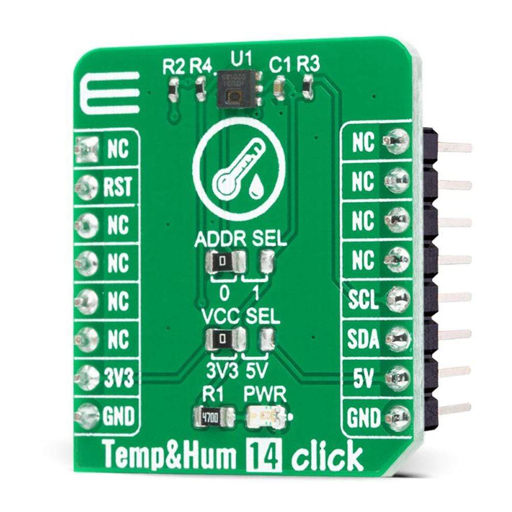
Temp&Hum 14 Click Board
Couldn't load pickup availability
The Temp & Hum 14 Click Board™ is a compact add-on board that contains one of the smallest and most accurate humidity and temperature sensors on the market. This board features the HTU31D , a highly accurate digital relative humidity sensor with temperature output from TE Connectivity Measurement Specialties. With power consumption down to 3.78μW and accuracy of ±2%RH and ±0.2°C, this Click Board™ provides fast response time, precision measurement, low hysteresis, and sustained performance even when exposed to extreme temperature up to 125°C and humidity environments.
The Temp & Hum 14 Click Board™ is suitable for relative humidity and temperature measuring applications, including weather stations, reliable monitoring systems, and more. Temp & Hum 14 Click is supported by a mikroSDK compliant library, which includes functions that simplify software development. This Click Board™ comes as a fully tested product, ready to be used on a system equipped with the mikroBUS™ socket.
How Does The Temp & Hum 14 Click Board™ Work?
The Temp & Hum 14 Click Board™ is based on the HTU31D, a digital relative humidity sensor with temperature output from TE Connectivity. Both sensors inside of the HTU31D are individually calibrated, compensated, and tested. The humidity can be measured within a range of 0 to 100 %RH, while the temperature sensor is designed for a range of -40 to 125 °C. The typical accuracy for humidity is ± 2 %RH in the measuring range of 20 up to 100 %RH at ambient temperature and ±0.2 °C for temperature between 0 - 100 °C with power consumption down to 3.78μW.
.jpg)
This Click Board™, an I2C configurable environmental sensor, is characterized by high reliability and full interchangeability with no calibration required in standard conditions. It has a quick recovery time after long periods in the saturation phase, low power consumption, and fast response time. Also, this sensor provides sustained performance even when exposed to extreme temperatures up to 125°C and humidity environments.
The Temp & Hum 14 Click Board™ communicates with MCU using the standard I2C 2-Wire interface with a maximum frequency of 10MHz. The HTU31D can answer 2 I2C addresses and allows the choice of the least significant bit (LSB) by positioning SMD jumpers labelled as ADDR SEL to an appropriate position marked as 0 and 1. In addition to this feature, this Click board™ also contains additional functionality routed to the RST pin on the mikroBUS™ socket. The RST pin can be used to generate a reset of the sensor with a minimum pulse duration of 1 μs required to trigger this function.
The HTU31D also offers a diagnostic register that can be used to check whether the values for humidity and temperature are outside the specified range. The CRC check (Cyclic Redundancy Check) ensures secure data transmission. The humidity and temperature signal response time, as well as the recovery time (after complete condensation), are within a range of a few seconds.
The Temp & Hum 14 Click Board™ is designed to be operated with both 3.3V and 5V logic voltage levels that can be selected via VCC SEL jumper. This allows for both 3.3V and 5V capable MCUs to use the I2C communication lines properly. However, the Click board™ comes equipped with a library that contains easy to use functions and an example code that can be used as a reference for further development.
SPECIFICATIONS
| Type | Temperature & humidity |
| Applications | Can be used for relative humidity and temperature measuring applications, including weather stations, reliable monitoring systems, and more. |
| On-board modules | The Temp & Hum 14 Click Board™ is based on the HTU31D, a digital relative humidity sensor with temperature output from TE Connectivity. |
| Key Features | High reliability and environmental robustness, full interchangeability with no calibration required in standard conditions, quick recovery after long periods in saturation phase, low power consumption, fast response, and more. |
| Interface | I2C |
| Compatibility | mikroBUS |
| Click board size | S (28.6 x 25.4 mm) |
| Input Voltage | 3.3V or 5V |
PINOUT DIAGRAM
This table shows how the pinout of the Temp & Hum 14 Click Board™ corresponds to the pinout on the mikroBUS™ socket (the latter shown in the two middle columns).
| Notes | Pin | Pin | Notes | ||||
|---|---|---|---|---|---|---|---|
| NC | 1 | AN | PWM | 16 | NC | ||
| Reset | RST | 2 | RST | INT | 15 | NC | |
| NC | 3 | CS | RX | 14 | NC | ||
| NC | 4 | SCK | TX | 13 | NC | ||
| NC | 5 | MISO | SCL | 12 | SCL | I2C Clock | |
| NC | 6 | MOSI | SDA | 11 | SDA | I2C Data | |
| Power Supply | 3.3V | 7 | 3.3V | 5V | 10 | 5V | Power Supply |
| Ground | GND | 8 | GND | GND | 9 | GND | Ground |
ONBOARD SETTINGS AND INDICATORS
| Label | Name | Default | Description |
|---|---|---|---|
| LD1 | PWR | - | Power LED Indicator |
| JP1 | VCC SEL | Left | Power Supply Voltage Selection 3V3/5V: Left position 3V3, Right position 5V |
| JP2 | ADDR SEL | Left | Communication interface selection: Left position 0, Right position 1 |
TEMP&HUM 14 CLICK ELECTRICAL SPECIFICATIONS
| Description | Min | Typ | Max | Unit |
|---|---|---|---|---|
| Supply Voltage | -0.3 | - | 6 | V |
| Current consumption | - | - | 0.45 | mA |
| Humidity Operating Range | 0 | - | 100 | %RH |
| Relative Humidity Accuracy | - | ±2 | - | %RH |
| Temperature Accuracy | - | ±0.2 | - | °C |
| Operating Temperature Range | -40 | - | +125 | °C |
Software Support
We provide a library for the Temp & Hum 14 Click Board™ on our LibStock page, as well as a demo application (example), developed using MikroElektronika compilers. The demo can run on all the main MikroElektronika development boards.
Library Description
The library covers all the necessary functions to control Temp&Hum 14 Click board™. Library performs a standard I2C interface communication.
Key Functions
void temphum14_set_conversion ( uint8_t hum_osr, uint8_t temp_osr )- Set conversion function.void temphum14_get_diagnostic ( temphum14_diagn_t *diag_data )- Get diagnostic status function.void temphum14_get_temp_and_hum ( float *temp, float *hum )- Get temperature and humidity data function.
Example Description
The application is composed of three sections :
- System Initialization - Initializes I2C, set RST as output and start to write log.
- Application Initialization - Initialization driver enables - I2C, hardware reset the device and read the serial number, also write log.
- Application Task - (code snippet) This is an example that demonstrates the use of the Temp & Hum 14 Click board™. Temp & Hum 14 Click board™ can be used to measure temperature and relative humidity. All data logs write on USB UART changes every 3 sec.
void application_task ( )
{
 temphum14_set_conversion( TEMPHUM14_CONVERSION_HUM_OSR_0_020,
 TEMPHUM14_CONVERSION_TEMP_0_040 );
 Delay_ms( 10 );
 temphum14_get_temp_and_hum( &temperature, &humidity );
 Delay_ms( 10 );
 FloatToStr( temperature, log_text );
 mikrobus_logWrite( " Temperature : ", _LOG_TEXT );
 mikrobus_logWrite( log_text, _LOG_TEXT );
 mikrobus_logWrite( " C", _LOG_LINE );
 FloatToStr( humidity, log_text );
 mikrobus_logWrite( " Humidity : ", _LOG_TEXT );
 mikrobus_logWrite( log_text, _LOG_TEXT );
 mikrobus_logWrite( " %", _LOG_LINE );
 mikrobus_logWrite( "-----------------------------", _LOG_LINE );
 Delay_ms( 3000 );
}
Additional Functions :
- void display_diagnostic ( void ) - Display diagnostic.
The full application code, and ready to use projects can be found on our LibStock page.
Other mikroE Libraries used in the example:
- I2C
- UART
- Conversions
Additional Notes and Information
Depending on the development board you are using, you may need USB UART Click Board™, USB UART 2 Click Board™ or RS232 Click Board™ to connect to your PC, for development systems with no UART to USB interface available on the board. The terminal available in all MikroElektronika compilers, or any other terminal application of your choice, can be used to read the message.
MIKROSDK
The Temp & Hum 14 Click Board™ is supported with mikroSDK - MikroElektronika Software Development Kit. To ensure proper operation of mikroSDK compliant Click board™ demo applications, mikroSDK should be downloaded from the LibStock and installed for the compiler you are using.
Temp&Hum 14 Click Board
Frequently Asked Questions
Have a Question?
Be the first to ask a question about this.